📡 Fractional Bandwidth Calculator
Calculate FBW, Q-factor, absolute bandwidth & system classification for RF, antenna & microwave systems
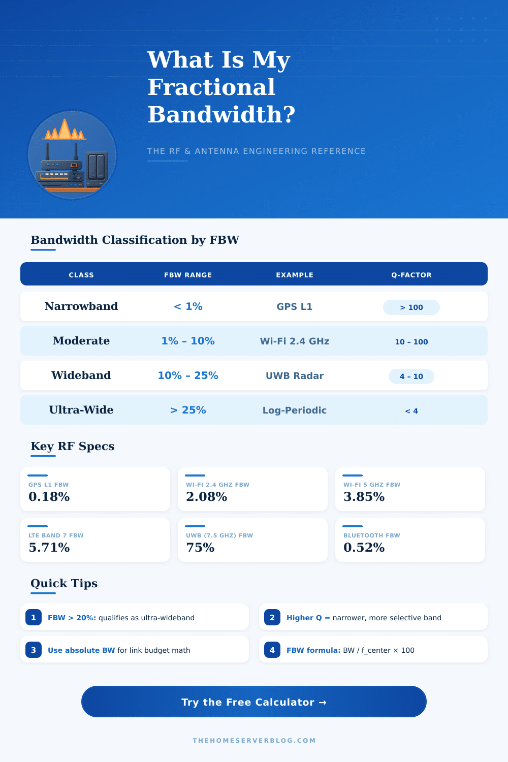
| Class | FBW Range | Q-Factor Range | Typical Example | IEEE Category |
|---|---|---|---|---|
| Narrowband | < 1% | > 100 | GPS L1, Crystal Filters | Narrowband |
| Moderate | 1% – 5% | 20 – 100 | Wi-Fi, Bluetooth, LTE | Moderate Bandwidth |
| Wideband | 5% – 20% | 5 – 20 | DAB, Radar, 5G NR | Wideband |
| Ultra-Wideband | 20% – 100% | 1 – 5 | UWB, Log-Periodic Ant. | Ultra-Wideband |
| Super-Wideband | > 100% | < 1 | Impulse Radar, TEM Horn | Super-Wideband |
| System | Center Freq | Bandwidth | FBW | Q-Factor | Class |
|---|---|---|---|---|---|
| GPS L1 | 1575.42 MHz | 2.046 MHz | 0.13% | 770 | Narrowband |
| AM Radio | 1 MHz | 10 kHz | 1.0% | 100 | Narrowband |
| FM Radio | 100 MHz | 200 kHz | 0.2% | 500 | Narrowband |
| Bluetooth 5 | 2441 MHz | 83.5 MHz | 3.42% | 29.2 | Moderate |
| Wi-Fi 2.4 GHz | 2450 MHz | 83.5 MHz | 3.41% | 29.3 | Moderate |
| Wi-Fi 5 GHz | 5500 MHz | 500 MHz | 9.09% | 11.0 | Wideband |
| LTE Band 7 | 2650 MHz | 70 MHz | 2.64% | 37.9 | Moderate |
| 5G NR n77 | 3700 MHz | 800 MHz | 21.6% | 4.6 | Ultra-Wideband |
| X-Band Radar | 9500 MHz | 500 MHz | 5.26% | 19.0 | Wideband |
| UWB (IR-UWB) | 6500 MHz | 1500 MHz | 23.1% | 4.3 | Ultra-Wideband |
| Formula / Parameter | Expression | Notes | Standard |
|---|---|---|---|
| Fractional Bandwidth | FBW = BW / f₀ × 100 | f₀ = center frequency | IEEE Std 149 |
| Q-Factor from FBW | Q = f₀ / BW = 100 / FBW | Higher Q = narrower band | IEEE Std 100 |
| Center Frequency | f₀ = (f₁ + f₂) / 2 | Arithmetic mean | IEEE / ITU-R |
| Geometric Center Freq | f₀ = √(f₁ × f₂) | Used for ultra-wideband | FCC 02-48 |
| UWB FCC Definition | FBW ≥ 20% or BW ≥ 500 MHz | At –10 dB power level | FCC Part 15.517 |
| Return Loss (VSWR) | RL = 20 log₁₀((VSWR+1)/(VSWR–1)) | VSWR 2:1 ≅ –9.5 dB | IEEE Std 149 |
| BW from Q | BW = f₀ / Q | 3 dB bandwidth | IEEE Std 100 |
| Relative Bandwidth | RBW = (f₂ – f₁) / f₀ | Dimensionless (0–2) | ITU-R SM.1542 |
| Project / Scenario | Center Freq | Bandwidth | FBW | Classification |
|---|---|---|---|---|
| Home Wi-Fi Router Dual Band | 3975 MHz | 583.5 MHz | 14.7% | Wideband |
| Amateur Radio HF (20m band) | 14175 kHz | 350 kHz | 2.47% | Moderate |
| Drone Video Link 5.8 GHz | 5800 MHz | 150 MHz | 2.59% | Moderate |
| Satellite Ku-Band Downlink | 11950 MHz | 500 MHz | 4.18% | Moderate |
| Point-to-Point Microwave | 11200 MHz | 56 MHz | 0.5% | Narrowband |
| RFID UHF Reader | 915 MHz | 26 MHz | 2.84% | Moderate |
fractional bandwidth helps to estimate how far a genuinely wideband antenna or signal is… It shows you how spread the frequencies are around the central value. Here the idea in basic words: one takes the difference between the highest and lowest frequencies later splits that by the central frequency.
Like this one gets the fractional bandwidth.
What Is Fractional Bandwidth?
There are some different ways to write the math. One method uses the absolute bandwidth split by the central frequency. A second way doubles the difference between the upper and lower frequency limits, and later splits that by the sum of those limits.
Both ways lead to the same result, and one can show it as a fraction or as a percentage.
So, why not simply use clear absolute bandwidth? Here is the problem… Say, that a filter has 1 kHz of bandwidth, that does not tell you a lot without context.
Whether that filter works at 5 kHz or at 5 MHz? Those 1 kHz becomes a totally different engineering challenge depending on where it sits. Right here the fractional bandwidth comes to help.
It gives you the whole picutre.
If a signal has big fractional bandwidth, for instance 50% or more, it covers quite a wide range of frequencies around its centre. Ultra-wideband (UWB) signals are the typical example for that. They have very high fractional bandwidth compared to typical narrowband systems, which makes them ideal for fast wireless uses.
Here is something neat: any frequency strip of a given width carries the same data volume, regardless of its position in the spectrum. A signal of 100 MHz width carries data at the same speed, whether centered at 100 MHz or at 5.8 GHz. The reason that higher frequencies commonly mean bigger bandwidths comes from this idea of fractional bandwidth.
In ultrasound devices the whole bandwidth that a sensor captures holds several weak signals that get lost in the background noise and thus become useless. Practical is the fractional bandwidth, that focuses on what truly is useful in that range.
Antenna designs play a big role hear. A thicker dipole relative to its wavelength offers more bandwidth than a thin version. Surprisingly, the bandwidth depends on the thickness of the conductor.
Consider a dipole designed for the 2-meter band from thick copper tubing; it reaches fractional bandwidth around 15% thanks to the much shorter wave and the heavy material.
The quality factor (Q) in a resonant circuit is actually the inverse of the fractional bandwidth, when one considers the power across frequency. If one raises Q, the bandwidth narrows for a fixed resonant frequency. Small electrical antennas meet troubles, because the input impedance changes quickly across frequencies, which limits the useful bandwidth.
Even so, if you know the impedance values across your frequency range, you can figure out thefractional bandwidth from VSWR directly.
fractional bandwidth also appears commonly in discussions about bandwidth ratio. A percentage like 20% matches a ratio of 1.22:1, while 30% matches something different. It is simply another viewpoint for seeing the same thing.