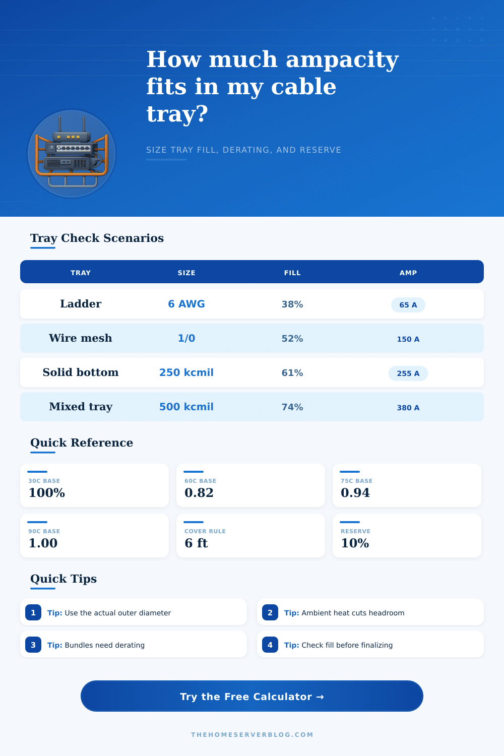
Cable Tray Ampacity Calculator
Size tray fill, ambient derating, bundled conductors, and design reserve with a code-minded planning tool for home labs, feeds, and workshop runs.
| NEC Rule | Typical Condition | Planning Factor | Practical Note |
|---|---|---|---|
| 392.80(A)(1) | Multiconductor tray cable | 310.16 / 310.18 | Apply only if more than 3 CCC |
| 392.80(A)(2)(a) | 600 kcmil and larger singles | 75% open, 70% covered | Use tray width and cover length |
| 392.80(A)(2)(b) | 1/0 through 500 kcmil singles | 65% open, 60% covered | Hot runs need extra reserve |
| 392.80(A)(2)(c) | Single layer with spacing | Free-air style planning | Keep about one diameter open |
| 392.22 fill | Tray occupancy check | Width or area limit | Mixed loads add up quickly |
| Conversion | Imperial | Metric | Rule of Thumb |
|---|---|---|---|
| Tray width | 6 in | 150 mm | Small ladder tray |
| Cover threshold | 6 ft | 1.8 m | Continuous cover changes ampacity |
| Spacing rule | 1 OD | 1 cable dia | Open spacing helps cooling |
| Square spacing | 2.15 OD | 2.15 dia | Triangular or square bundles |
| Project | Cable mix | Tray width | Design check |
|---|---|---|---|
| Home lab feed | 6 AWG x 3 | 4 in | 65 A class |
| Camera trunk | 10 AWG x 4 | 6 in | 75 A class |
| Server spine | 1/0 x 2 | 12 in | 150 A class |
| Workshop feeder | 250 kcmil x 3 | 18 in | 250 A class |
Keep OD honest: the tray sees outside diameter, not conductor gauge.
Heat stacks up: ambient, cover length, and bundles all lower headroom.
Cable tray ampacity refer to the maximum amount of current that a cable tray system can handles. Calculating the ampacity of a cable tray is essential because if the requirement for the cable tray are not properly calculated, there will be an excess amount of heat built up within the tray system. The high amount of electrical currents that passes through the tray and the amount of heat that is dissipated from the system cause an excess amount of heat within the cable tray system.
If the amount of heat that the cables create exceed the amount of heat that the cable tray system can dissipate, then the cables will overheat. This can happen if the ambient temperature in the cable tray system is high or if the cable tray system are covered. The type of cable tray system that is use will change the ampacity limits of the tray system.
How to Calculate Cable Tray Ampacity
If someone uses open ladder cable trays, air can circulate around the cables, which will increase the ampacity limits of the tray system for single conductor. If someone use solid bottom cable trays, there will be less airflow around the cables, which will reduce the ampacity limits of the tray system for multiconductor cables. The type of cable that is use in the tray will also change the ampacity limits of the cable tray system.
If MC or TC-ER cables is used, the thicker jackets that surround the conductors of these cables will take up more space within the cable tray than single conductors will take up in the same tray. This will limit the numbers of cables that can be placed into the tray system. The ambient temperature of the area where the cables will be installed will also change the ampacity limits of the tray system.
If the ambient temperature of the workspace is hotter then the baseline temperature, the ampacity limits of the tray system will have to be reduced. This is to accommodate the higher ambient temperature that will reduce the ability of the cables to remain cool. Additionally, if there are more than three current carrying cables in a bundle within the tray system, the ampacity limits of the tray system will have to be reduced.
The process of reducing the ampacity limits of the tray system is called derating, and this is done to prevent the cables from overheating. Additionally, if covers is used on a cable tray system that is longer than six feet, the ampacity limits of the tray system will have to be reduced because the covers will trap heat within the tray. When calculating the ampacity limits of a tray system, it is necessary to include a design reserve.
A design reserve for cable tray system is between 10% and 20% of the calculated ampacity limits of the tray system. This reserve is included to allow for voltage drop within the system and to account for any future electrical load that may be added to the cables. Including a design reserve allows the cables to remain within a range that is lesser than the ampacity limits of the tray system.
The width of the cable tray and the diameter of the cables that will be used in the tray system must also be considered in the calculation of the ampacity limits of the tray system. The diameter of the cables will determine the amount of space that the cables will take up in the tray system. The width of the tray will determine how many of these cable can be incorporated into the tray.
If aluminum cable trays is to be used, it is important to account for the lower conductivity of aluminum compared to copper. Many people make mistake when calculating the ampacity limits of a tray system, such as using the gauge of the bare conductor instead of the outer diameter of the cable. The outer diameter of the cable is what should be use in the calculation to determine how much space the cable will take up in the tray system.
Additionally, another mistake that people make is to mix control cables with power cables in a manner that would exceed the limits of the space that the tray system can take up. Following these steps and correctly calculating the ampacity limits of a tray system with a proper design reserve will allow the cables to remain safe within the tray system without overheating.