Link Budget Calculator
Estimate EIRP, free-space path loss, received signal, fade margin, Fresnel clearance, and wireless link reliability for home lab point-to-point and sensor links.
⚙️Link presets
📶RF link inputs
📊Current profile specs
📘Band and antenna reference
| Radio profile | Useful range | Typical antenna | Practical planning note |
|---|---|---|---|
| 2.4 GHz Wi-Fi | Room to yard | 5 to 12 dBi | Better foliage tolerance, more interference in dense neighborhoods. |
| 5 GHz bridge | Yard to campus | 13 to 25 dBi | Excellent for directional links with clean line of sight. |
| 6 GHz Wi-Fi 6E | Indoor short hop | 2 to 8 dBi | High bandwidth, but wall and distance losses add quickly. |
| 900 MHz sensor | Property scale | 2 to 9 dBi | Lower speed, strong range for telemetry and control links. |
| 60 GHz link | Short roof hop | 30 to 43 dBi | Very high path loss; alignment and rain margin matter. |
📏Capacity by configuration
| Configuration | Recommended margin | Fresnel clearance | Best use |
|---|---|---|---|
| Indoor room-to-room | 8 to 12 dB | Not usually modeled | Fast checks through one or two light partitions. |
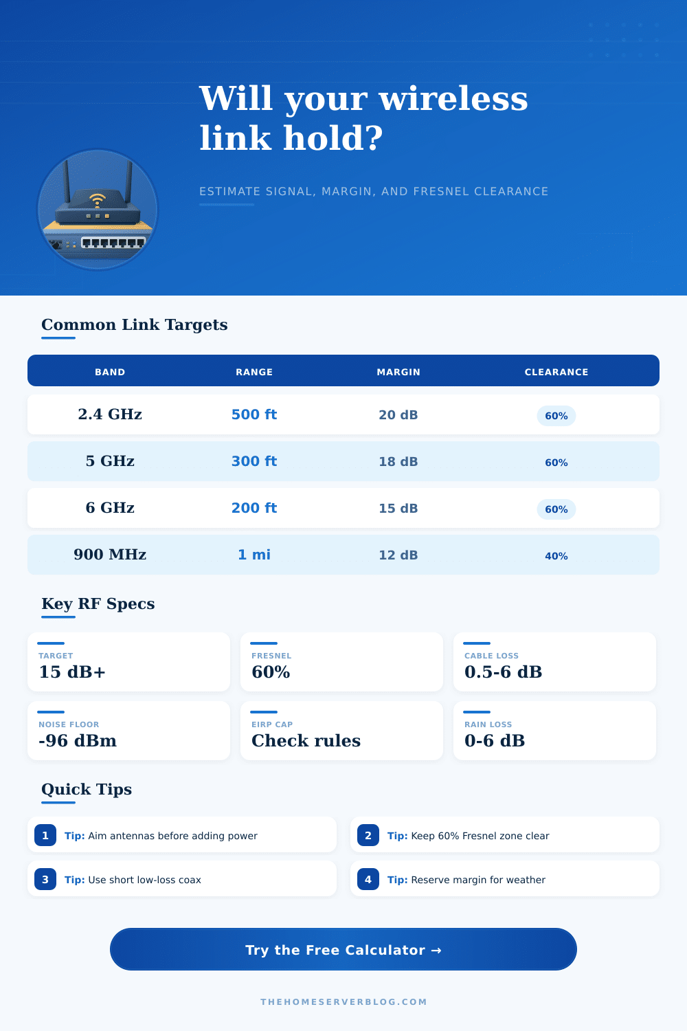
| Outdoor PtP bridge | 15 to 25 dB | 60% clear | Detached garage, workshop, or homelab backhaul. |
| Point-to-multipoint AP | 18 to 30 dB | 60% clear | Several clients sharing one sector or omni AP. |
| Low-power sensor | 10 to 20 dB | 40% to 60% | Telemetry where throughput is less important than reach. |
| 60 GHz roof link | 20 to 35 dB | Clear LOS | Short, aligned, high-throughput outdoor spans. |
🔢Standards and formulas
| Item | Formula or value | Unit | How this calculator uses it |
|---|---|---|---|
| Free-space path loss | 32.44 + 20 log km + 20 log MHz | dB | Calculates clear-air attenuation across the entered path. |
| EIRP | TX power - TX loss + antenna gain | dBm | Shows effective radiated power before path loss. |
| Received signal | EIRP - FSPL - fade + RX gain - RX loss | dBm | Compares predicted signal to receiver sensitivity. |
| Thermal noise | -174 + 10 log bandwidth + NF | dBm | Estimates SNR from bandwidth and receiver noise figure. |
| Fresnel midpoint | 17.32 sqrt(d1 d2 / f d) | meters | Estimates the first Fresnel radius at link midpoint. |
🏠Common home lab link sizes
| Project | Distance | Typical band | Starting target |
|---|---|---|---|
| Detached garage bridge | 150 to 500 ft | 5 GHz | 15 dB margin, 60% Fresnel clear. |
| Backyard camera | 100 to 800 ft | 2.4 or 5 GHz | Plan extra loss for foliage and mounting height. |
| Workshop AP uplink | 200 to 1,200 ft | 5 GHz | Directional antennas beat raw transmit power. |
| Barn sensor node | 0.25 to 2 mi | 900 MHz | Use lower bandwidth and higher fade margin. |
| Roof-to-roof backhaul | 0.1 to 1 mi | 5 or 60 GHz | Confirm clear LOS before selecting radios. |
💡Planning notes
A wireless links between two points can becomes unstable due to changes in an environment. Many people believes that a wireless link between two locations require a visual link between the two locations. However, a visual link is not sufficient to create a stable wireless link.
Wireless links can fail due to rain in the area between the two locations, the growth of trees between the two locations, or due to physical obstacle between the two locations that interfere with the radio waves that are transmit between those two locations. In order to create a stable wireless link, you must understand the link budget and the Fresnel zone, as must the effects of frequency and the effects of cable between the two locations. The link budget is the calculation of the amount of signal power that are available to the wireless link.
How to Keep a Wireless Link Stable
The technician calculates the link budget by taking the transmit power of the signal, the gain of the antenna, and then the loss of that signal as it is transmit through the air. The transmit power and the antenna gain combines to create the effective radiated power of the signal. The loss of signal power as it travel through the air is referred to as the free space path loss.
If the power of the signal remaining after it has traveled through the air is higher than the minimum signal power require by the receiver at the destination location, the link will be successful. However, if the power of the signal remaining after it has traveled through the air is very close to the minimum signal power required by the receiver, the link will be unstable. The difference between the power of the received signal and the minimum required signal power is referred to as a fade margin.
A large fade margin creates a buffer for the wireless link to withstand weather and interference in the environment. A small fade margin make the link vulnerable to failure. The Fresnel zone is an elliptical area around the line of sight between the two antenna.
Many people may believe that the line of sight between the two antennas is all that is required for the link to be established. However, the line of sight is not sufficient if buildings, hills, trees, or any other obstacle obstruct the Fresnel zone. Radio waves do not travel in a thin line between the two antennas.
The radio waves travel in an elliptical shape, often referred to as a football shape. Any obstruction within the Fresnel zone can reflect the radio waves from one antenna to the other. The reflected radio waves may interfere with the incoming radio waves which create signal cancellation which can lead to the wireless link failing between the two locations.
The Fresnel zone must remain clear of any obstacle for the link to remain stable. The frequency of the wireless link has an effect on how the signal travels between the two locations. Links using lower frequencies are able to travel around obstacles between the locations and through foliage more easy than links using higher frequencies.
Lower frequencies are generally used for establishing links between locations that are more than a few mile apart. Higher frequencies, such as 5 GHz or 60 GHz, allow for the transmission of more data through the link. However, higher frequencies is considered more fragile than lower frequencies.
For instance, heavy rain can absorb the signal of a 60 GHz wireless link which will cause that link to cease function until the rain clears. Any cables between the antennas will cause a loss of signal power. Any foot of coaxial cable between the antennas introduces a loss of signal power.
The same is true for every connector that the signal passes through. Losses in signal power are measure in decibels. A loss of 3 dB is equivalent to a 50% reduction in signal power.
Using shorter cables and cables with less loss than others is generally more effective in increasing the signal strength than increasing the transmit power of the radio emitting the signal. When establishing a wireless link, the link should not be established if it is likely that the signal power will only barely meet the requirements of the receiver at the destination. Instead, the link should be established with a large fade margin to allow for the link to withstand misalignment between the antennas and to withstand interference and weather condition.
By planning the link budget and the Fresnel zone for the link during the planning stage, the link will remain stable.