Fresnel Zone Calculator
Plan point-to-point wireless clearance for Wi-Fi bridges, WISP links, cameras, sensors, and home lab backhaul paths using first Fresnel zone, earth bulge, and obstruction math.
Calculation Breakdown
| Configuration | Typical Band | Useful Path | Clearance Planning Note |
|---|---|---|---|
| Home office to detached garage | 5 GHz or 6 GHz | 0.05 to 0.5 mi / 0.08 to 0.8 km | Usually rooftop height is enough unless trees cross the midpoint. |
| Farm camera or barn network | 2.4 GHz, 5 GHz, or CBRS | 0.2 to 2 mi / 0.3 to 3.2 km | Lower frequencies tolerate foliage better but need larger Fresnel clearance. |
| WISP subscriber or backhaul spur | 5 GHz, 11 GHz, or licensed microwave | 1 to 8 mi / 1.6 to 12.9 km | Include earth bulge and survey buffer before ordering mounts. |
| Rooftop mmWave hop | 24 GHz or 60 GHz | 0.03 to 0.6 mi / 0.05 to 1 km | The Fresnel zone is compact, but line of sight and rain fade matter more. |
| Reference | Value | Where It Applies | Practical Limit |
|---|---|---|---|
| First Fresnel zone | n = 1 | Primary RF clearance zone | Keep at least 60% clear for a reliable design target. |
| Wavelength | 299.792 / f MHz | Radius calculation | Higher frequencies have shorter wavelengths and smaller zones. |
| Earth K factor | 4/3 common | Longer outdoor paths | Use K = 1 for a conservative no-refraction check. |
| Distance conversion | 1 mi = 1.609 km | Survey maps and GPS | Keep all internal math in meters to avoid mixed-unit mistakes. |
| Height conversion | 1 ft = 0.3048 m | Tripods, poles, and roof masts | Round mount recommendations upward, not downward. |
| Project | Equipment Count | Primary Result to Watch | Secondary Result to Watch |
|---|---|---|---|
| Small home lab garage bridge | 2 bridge radios, 1 switch | 60% Fresnel radius at the roof edge | Clearance above parked vehicles and gutter line |
| Detached office Wi-Fi extension | 2 directional APs, 1 indoor AP | Actual clearance percentage at trees | Extra mast height needed on either side |
| Farm camera backhaul | 2 radios, 2 cameras, 1 PoE switch | Obstacle intrusion from canopy and terrain | Earth bulge on paths longer than one mile |
| Neighborhood WISP spur | 2 dishes, 1 router, 1 UPS | Midpoint Fresnel zone and survey buffer | Single-end raise needed if one roof is fixed |
A wireless bridge is a device that allow for the transmission of internet signals between two location. A wireless bridge does, however, require a clear path for the radio waves to travel from one bridge antenna to the other. It is possible that there is a clear visual line of sight between the two antennas that the wireless bridge are to be link; however, visual line of sight is not the same than line of sight for the radio frequency (RF) waves that emanate from the antennas.
While a person can visual see from one antenna to the next, the RF waves do not travel in the same manner as a laser beam; they travel in an elliptical shape. This elliptical shape are referred to as the Fresnel zone. The Fresnel zone is an invisible zone of air that exist between the two antennas.
Keep the Fresnel Zone Clear for a Strong Wireless Bridge
The Fresnel zone must remain clear of any obstructions to the wireless bridge connection. Should an object enter the Fresnel zone, the RF waves will reflect off of that object. These reflected RF waves reach the receiving antenna at a different time then the RF waves that traveled directly from one antenna to the other.
These reflected waves can interfere with the incoming RF waves; this phenomenon is known as destructive interference. Destructive interference can cause the wireless bridge connection to drop packet or lose speed. Therefore, objects should not enter the elliptical Fresnel zone create by the two antennas.
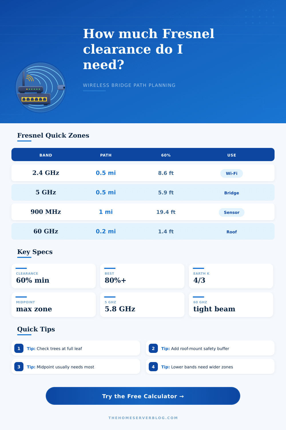
The size of the Fresnel zone into which an object should not enter is related to the frequency at which the wireless bridge operate. Frequencies like 2.4 GHz have wavelengths that are long than frequencies like 60 GHz. RF waves at 2.4 GHz will create a Fresnel zone that is wider than the Fresnel zone created by 60 GHz RF waves.
Therefore, a wireless bridge at 2.4 GHz will require more clearer air and space around the antennas; however, the 2.4 GHz RF waves have the ability to bend around small obstacle in their path. On the other hand, the 60 GHz wireless bridge will behave more like a tight needle in that the RF waves will not bend around obstacles; the path must be clear of any obstructions. Thus, there is a trade-off between the reach of the wireless bridge and the precision of the wireless bridge.
When planning a wireless bridge between two locations, the Fresnel zone will be the widest in the middle of the antennas. Thus, any object located in the middle of the Fresnel zone is more of a danger to the wireless bridge than an object located near one of the antennas. For instance, a fence located in the middle of the Fresnel zone may destroy the throughput of the wireless bridge, but a shed located near one of the antennas may not impact the signal strength.
In addition to the Fresnel zone, the curvature of the earth can impact the wireless bridge. The earth curves upward over long distances. Therefore, for short distance there is no problem created by the curvature of the earth; for long distances, the curvature of the earth is an obstruction to the path of the wireless bridge.
To calculate the effect that the curvature of the earth have on the path of the RF waves, engineers use a K factor. The standard K factor for curvature of the earth is 4/3. To ensure that the wireless bridge create a stable connection between the two locations, engineers may use a K factor of 1.0.
Thus, the most effective way to ensure that there is no interference between the two antennas of a wireless bridge is to ensure that there is enough height for the antennas. Most engineers want to ensure that there is at least 60 percent of the Fresnel zone clear of any obstructions. Many engineers, however, aim for 80 percent of the Fresnel zone clear of any obstructions.
If engineers ensure 80 percent of the Fresnel zone is free of any obstructions, the wireless bridge will be able to handle seasonal change that may occur, like trees growing leaves. The foliage between the antennas can pose a problem for the wireless bridge because the water in the leaves absorb some of the RF energy radiated from the antennas; the absorption of that RF energy by the water will weaken the signal. Finally, another consideration for wireless bridges includes the margin in which the wireless bridge is to be construct.
There will be errors in the GPS coordinates of each of the antennas, and there will be error in the way in which the antennas are mounted to the structures at each location. Therefore, engineers must provide some extra clearance in addition to that which is calculate for each of the antennas. If the calculations indicate that there is only a small margin for the antennas to remain within the Fresnel zone, the engineer is essentially gambling with the uptime of the wireless bridge connection.
Therefore, the plan must account for providing enough clearance of the Fresnel zone. By providing enough clearance for the Fresnel zone, the wireless bridge will provide stable connection for remote cameras or home lab wireless backhauls.