Radio Horizon Calculator
Estimate effective line-of-sight range, Fresnel clearance, Earth bulge, atmospheric K-factor impact, and fade-margin risk for home lab RF links, remote sensors, repeaters, and point-to-point bridges.
Formula Breakdown
| Scenario | Typical heights | Planning concern | Calculator setting |
|---|---|---|---|
| Roof gateway to LoRa field sensor | 35 ft to 8 ft | Tree lines close to the low sensor | 915 MHz, 60% Fresnel, 10 ft terrain clearance |
| House to barn Wi-Fi bridge | 28 ft to 24 ft | Mid-path ridge and summer foliage | 5800 MHz, 15% buffer, suburban profile |
| GMRS repeater to handheld edge | 80 ft to 6 ft | Receiver height controls most of the range | 462 MHz, conservative obstruction placement |
| Microwave short hop | 60 ft to 55 ft | Alignment, rain fade, and clear Fresnel | 11200 MHz, 20 dB or higher fade target |
| Formula or standard value | Expression | Use in this calculator | Practical note |
|---|---|---|---|
| Single-end radio horizon | dmi = 1.225 x sqrt(K x hft) | Calculated for both antennas and added | Assumes smooth Earth and height above local ground |
| First Fresnel radius | F1ft = 72.1 x sqrt(d1 x d2 / (GHz x D)) | Computed at the chosen obstruction point | Most links target at least 60% clear |
| Effective Earth bulge | Bulgeft = 0.667 x d1 x d2 / K | Subtracted from obstruction clearance | Bulge is largest near the middle of the path |
| Refractivity to K estimate | K = 157 / (157 + gradient) | Shown as a comparison against design K | Standard atmosphere is about -39 N-units/km |
| Frequency range | Example equipment | Fresnel behavior | Home lab planning note |
|---|---|---|---|
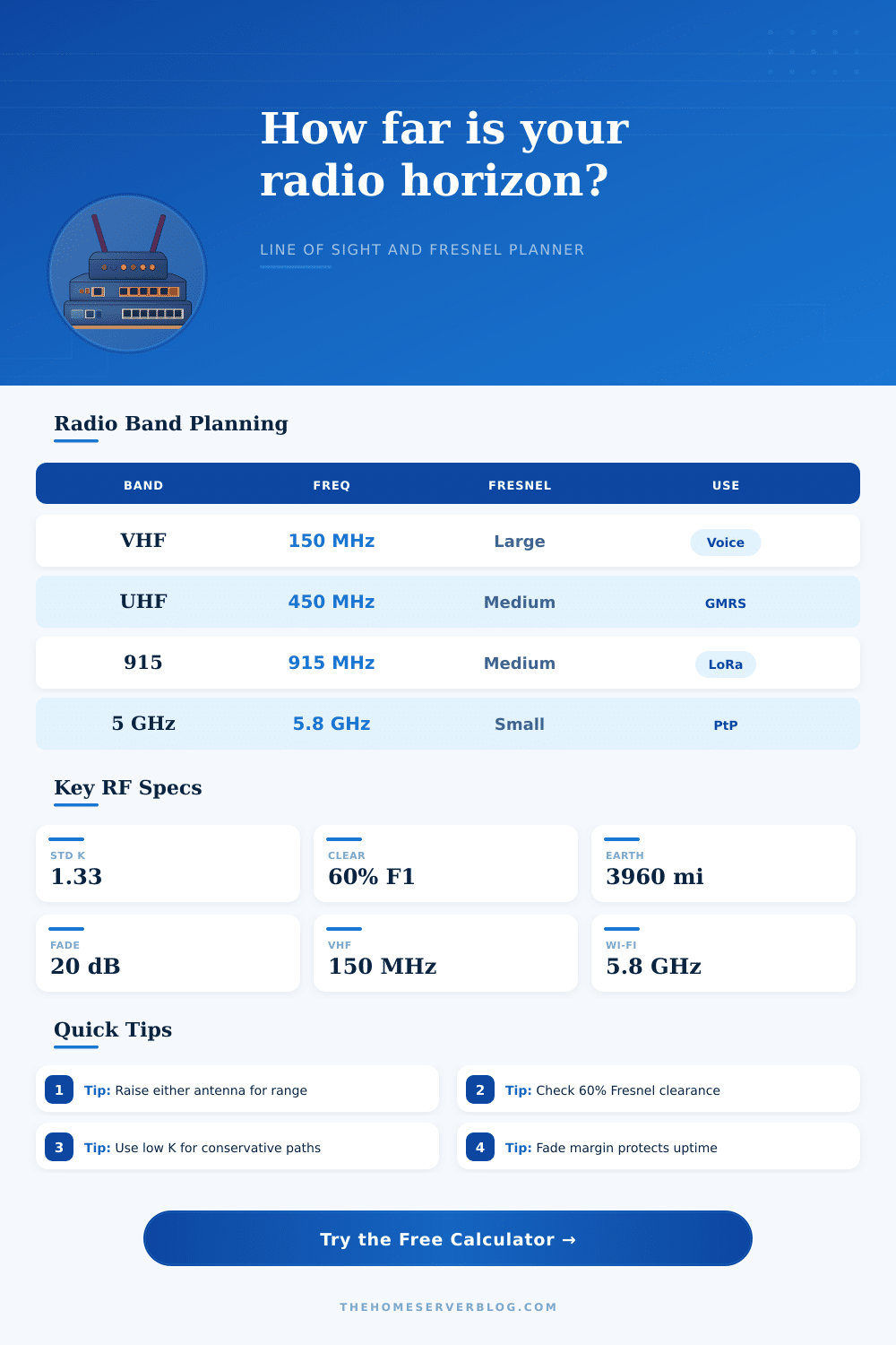
| 136-174 MHz | VHF mobile, APRS, marine | Large radius, more diffraction | Height matters; partial clutter may still work for voice |
| 420-470 MHz | GMRS, UHF business, sensors | Medium-large radius | Good for local repeaters and neighborhood coverage checks |
| 902-928 MHz | LoRa, 900 MHz mesh, telemetry | Medium radius | Balance of range, antenna size, and modest obstruction tolerance |
| 2400-6200 MHz | Wi-Fi, point-to-point bridges | Small radius but low diffraction | Keep the visual path clean; foliage losses can dominate |
| 10-11 GHz | Microwave dishes | Very small radius | Line of sight is strict; rain fade may set the margin |
| K-factor condition | Approx K | Effect on horizon | When to use it |
|---|---|---|---|
| Sub-refractive or conservative | 0.67 | Shorter horizon, larger bulge | Critical links, ducting-prone areas, low confidence surveys |
| Optical Earth | 1.00 | Geometric line-of-sight baseline | Compare radio results to simple visual horizon |
| Standard atmosphere | 1.33 | Common radio planning baseline | General home lab and WISP-style estimates |
| Super-refractive | 1.75+ | Longer apparent horizon | Do not rely on it for availability unless measured |
This planner is for engineering estimates. Final RF work should account for exact terrain profiles, antenna patterns, polarization, feedline loss, legal power limits, and measured noise floor.
Radio frequency planning require an understanding of the difference between visual line of sight and radio frequency line of sight. One may be able to see the targets that one aims to communicate with with the eyes, but the radio waves may not be able to reach that target. Radio waves does not travel in straight lines, and they require a clear corridor of space to properly function.
Without accounting for the path that the radio waves will take, the radio frequency link can either erratically function or fail complete. The K-factor is used to account for the curvature of an earth and how the atmosphere may bend the radio waves slightly downward. When calculating radio frequencies, the K-factor are multiplied by the distance between the two radio antennas.
Radio Line of Sight and the Fresnel Zone
The atmosphere bends the signal slightly downward, making the earth appear flatter to the radio waves than it do to human eyes. The most common K-factor is 1.33, which account for a typical atmosphere. However, the atmosphere is not always typical.
The atmosphere can be sub-refractive, causing the earth to appear bulging upward, which shrinks the horizons for the radio signal. Using a conservative K-factor during the planning of a radio frequency link accounts for the possible changes in humidity in the atmosphere. The Fresnel zone is an ellipsoidal area of energy between the two antennas.
Radio signals do not travel as thin laser beam, but as football-shaped areas of energy. Any object that enter the Fresnel zone will interfere with the transmission of the data signal. The objects interfere with the signal because they are obstructing the Fresnel zone.
The requirements for the Fresnel zone state that the engineer should keep 60% of the Fresnel zone clear of any obstructions. A calculator is available to determine the height and distances of the antennas that are to be used in the radio frequency link. The most important number indicated by the calculator is the net clearance of the Fresnel zone.
A negative net clearance for the Fresnel zone mean that the Earth or by foliage in the way of the signal will block the signal. Raising the antenna will increase the range of the radio signal. At the beginning of establishing a radio frequency link, raising the antenna will provide the most significant increase in range.
However, raising the antenna will provide diminishing return; the relationship between the raised antenna and range is based on a square root formula. The frequency of the radio signal will impact the size of the Fresnel zone. Lower frequencies, such as VHF radio frequencies, has larger Fresnel zones.
VHF signals diffract, which mean that they can bend over a hill, but high frequencies cannot. Higher frequencies, such as 5 GHz and 11 GHz, have much smaller Fresnel zone. However, the links made using high frequencies are more fragile.
High frequency radio signals are easily blocked by foliage, which means that trees can lead to packet loss of the radio frequency link using high frequencies. Fade margin indicate how much more signal strength the radio frequency link has than the minimum signal strength for the radio frequency equipment to function. Maintaining a healthy fade margin, such as a fade margin of 20 dB, indicates that the link has a buffer for unexpected event.
These unexpected events could be a heavy rainstorm that is reducing the signal strength of the link, or the erection of a fence that is blocking the signal strength. A low fade margin will result in an unreliable radio frequency link. A low fade margin indicates that the radio frequency link may fail during periods of bad weather.
Effective radio frequency planning requires one to account for the curvature of the earth and the Fresnel zone. One must manage expectation for radio frequency links, as the physics of the setup will determine the success of that link. However, if the radio frequency link is engineer properly, accounting for the bulge of the earth and the Fresnel zone, then the link will be easily established and remain stable.