Return Loss Calculator
Convert impedance mismatch, VSWR, or reflected power into return loss, reflection coefficient, mismatch loss, and practical link quality.
Impedance mode uses Gamma = (ZL - Z0) / (ZL + Z0), then return loss = -20 log10(|Gamma|).
Return Loss Results
| Return Loss | VSWR Approx. | Reflected Power | Practical Meaning |
|---|---|---|---|
| 30 dB or higher | 1.07:1 or better | 0.10% or less | Excellent lab termination or precision RF path |
| 20 dB | 1.22:1 | 1.00% | Strong feedline, antenna, or connector match |
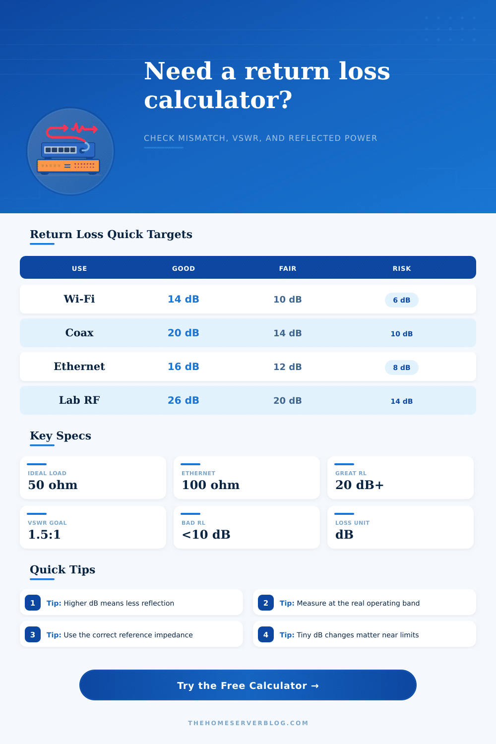
| 14 dB | 1.50:1 | 3.98% | Usually acceptable for many RF installs |
| 10 dB | 1.92:1 | 10.00% | Marginal match; inspect connectors and load |
| 6 dB | 3.01:1 | 25.12% | High reflection; likely performance or protection issue |
| Link Type | Reference Impedance | Typical Target | Notes |
|---|---|---|---|
| 50 ohm RF equipment | 50 ohms unbalanced | 14 to 20 dB | Common for Wi-Fi, SDR, LoRa, ham, and lab gear |
| 75 ohm coax distribution | 75 ohms unbalanced | 16 to 20 dB | Used for video, DOCSIS, satellite, and TV coax |
| Ethernet balanced pair | 100 ohms differential | 12 to 20 dB | Return loss varies with category, length, and frequency |
| SFP+ DAC twinax | 100 ohms differential | 15 dB or higher | Short passive cables need clean differential impedance |
| Precision bench path | 50 ohms unbalanced | 26 dB or higher | Useful for VNA calibration, attenuators, and terminations |
| Project | Equipment Count | Target Result | Secondary Check |
|---|---|---|---|
| Small SDR bench | 2 jumpers, 1 attenuator | 20 dB return loss | Mismatch loss below 0.05 dB |
| Outdoor LoRa gateway | 1 feedline, 2 adapters | 14 dB return loss | VSWR near 1.5:1 |
| DOCSIS service drop | 1 drop, 1 splitter | 16 dB return loss | Clean F connectors and 75 ohm terminators |
| Cat6 patch panel | 12 to 24 ports | 12 dB or better at high frequency | Keep pair twists and termination geometry intact |
| 10G short rack link | 2 SFP+ ports, 1 DAC | 15 dB return loss | Watch impedance discontinuities at the plug |
Return loss is a measurement that determine how much of the electrical signal reaches the destination and how much reflect back towards the source. When an electrical signal travel down a cable, some of the signal can reflect back towards the source when the impedance of the cable differ from that of the load. Impedance is an electrical measurement of the resistance of a circuit to an electrical signal.
An ideal system is one in which the impedance of the cable is the same than the load, in which case all of the power of the signal will enter the antenna or receiver. In most systems, however, the impedance of the cable and the load is not matched due to factors like poor crimps or incorrect type of cables being used. These changes in impedance cause the signal to reflect.
What is Return Loss?
Another value that is often used to measure the reflection of electrical signal is the Voltage Standing Wave Ratio (VSWR). VSWR is, however, often considered to be more difficult to use than return loss. The VSWR can be converted to the return loss of a system, which are measured in decibels.
Decibels are used to describe the ratio of power of two electrical signals. Thus, return loss is one of the more effective measurement of the health of a systems signal. A higher number in return loss, however, indicate a positive result to the system.
A high return loss value indicate that the signal is reaching the load, but little power are reflecting back towards the source. Thus, despite the fact that return loss is considered a positive measurement, the terminology used for the measurement is often confusing to those just learning of the concept. In order to calculate the return loss of a system, it is important to use the correct reference impedance.
For systems with standard RF (radio frequency) gear, 50 ohms is the correct reference impedance. For systems with cable or satellite TV gear, however, the reference impedance are 75 ohms. Any incorrect use of the reference impedance will provide an incorrect return loss measurement; therefore, it is important to ensure that the reference impedance match the type of equipment being evaluated.
In addition to evaluating return loss, it is also useful to determine the percentage of power that the load reflects back. For instance, a VSWR of 1.5:1 indicate that a certain percentage of the signal are reflected. For low-power system, this reflected power may not have a negative impact on the system; however, high-power systems that reflect power back towards the source can lead to the reflected power creating heat within the system.
This heat can degrade the systems component over time; thus, it is important to monitor the reflected power of high-power systems to ensure their components dont fails. Owing to the effects of reflected power, it is also important to measure the return loss for each of the systems frequency. Return loss at 100 MHz may be excellent for a system and cable, but the same system may have a poorly return loss at 2.4 GHz.
Return loss is affected by how high the frequency of the signal is; the higher the frequency, the more sensitive the system is to physical changes to the wire. Thus, any kink or defect in the wire will have a much more greater impact on a high-frequency signal than upon a low frequency signal. For these reason, it is essential to determine the return loss at the frequency at which the data will be transmitted.
Finally, it is important for a system to understand the concept of return loss in terms of the adequacey of return loss for the system. In other words, return loss do not have to be perfected for most systems; most systems do not require the same precision in return loss as, for example, military systems. At a certain decibel level in return loss, the signal loss is considered to be negligible, meaning that the system does not have to dedicate more time to improving the return loss of the signal.
By understanding return loss, a system can determine if it needs to replace its cables, or if the current return loss of the signal are within the parameter that is considered acceptable for its system. Youll also need to check if the cables is moddern enough to handle the load.