Fiber Link Budget Calculator
Estimate optical loss, receiver power, reserve margin, overload risk, and practical reach for home lab fiber runs.
⚡ Common Fiber Scenarios
💻 Link Configuration
Length is entered in feet.
Used only when custom optical budget is selected.
Fiber Budget Results
🔧 Current Link Data
📊 Fiber And Optic Reference
| Fiber or optic | Typical value | Home lab use | Budget note |
|---|---|---|---|
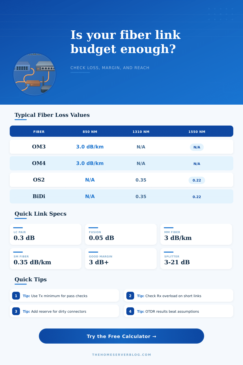
| OM3 or OM4 at 850 nm | About 3.0 dB/km | Short 10G or 40G runs | Distance limit usually matters before loss |
| OS2 at 1310 nm | About 0.35 dB/km | Garage, shed, riser, ISP hand-off | Good default for LR optics |
| OS2 at 1550 nm | About 0.22 dB/km | Longer ER or CWDM paths | Check receiver overload on short links |
| LC mated pair | 0.2 to 0.5 dB | Patch panels and wall plates | Use tested value when available |
| Fusion splice | 0.03 to 0.1 dB | Outdoor drops and pigtails | Mechanical splices may be higher |
📡 Transceiver Budget Guide
| Profile | Budget model | Common reach class | Practical check |
|---|---|---|---|
| 10GBASE-SR | Short-reach multimode | Up to hundreds of meters | Confirm OM rating and modal bandwidth |
| 10GBASE-LR | Singlemode 1310 nm | About 10 km class | Excellent for home outbuildings |
| 10GBASE-ER | Singlemode 1550 nm | About 40 km class | May need attenuation on very short paths |
| GPON class B+ style | High split budget | Lab PON shelves | Splitter loss dominates the math |
| CWDM lab link | Per-lambda budget | Depends on optic and mux | Add mux, demux, and patch losses |
📐 Common Project Sizes
| Project | Typical length | Passive items | Planning margin |
|---|---|---|---|
| Same rack SFP+ patch | 3 to 10 m | 2 connector pairs | Overload can matter more than loss |
| Home office to garage | 30 to 100 m | Wall plates and patch panel | 3 dB reserve is usually comfortable |
| House to detached shed | 75 to 250 m | Outdoor cable, splices, panels | Add allowance for repairs and dirt |
| PON bench lab | 10 to 500 m | 1:4 to 1:32 splitter | Splitter dominates total loss |
| CWDM home backbone | 50 m to 2 km | Mux, demux, patches | Check each wavelength separately |
💡 Link Planning Notes
An optical power budget is a calculation that determine whether a light signal has enough strength to make its journey from teh transmitter to the receiver. When you install a fiber optic cable system, you want to make sure that the signal from the transmitter reach the receiver with enough power for the receiver to read the signal. If there is too much loss of that signal between the transmitter and the receiver, then the link will either fail or it will become instability.
A link becomes unstable when there are fluctuation in the incoming light signal, and a link will fail if the strength of that signal falls too low for the receiver to read. In order to calculate the optical power budget, you must perform a process of subtraction. You start with the available power from the fiber optic transmitter.
How to Calculate an Optical Power Budget
From that starting point, you must subtract the loss of the fiber optic cable, the loss from the connectors, and the loss from the number of splices in the link. Each kilometer of fiber optic glass will cause a loss of optical power in decibels, as will each pair of male connectors that join the fiber optic cable together. If the total loss from the fiber, the connectors, and the splices is too great relative to the available power from the transmitter, then the signal will not be able to reach the receiver.
The type of fiber optic cable that you use will impact the amount of loss in your link. If you use singlemode fiber, you will experience less loss along the link than if you used multimode fiber. For instance, if you use OS2 singlemode fiber, your loss will be low; however, if you use OM4 multimode fiber, you will experience more higher loss.
Thus, the type of fiber that you use will impact your link loss, so you must account for that in your calculation of the optical power budget. Another factor in the optical power budget is the connectors that is used. Connectors will cause a loss of optical power in your link, and people refer to these losses as fixed losses.
Each pair of connectors will cause some loss of optical power, but using many connectors along your link will lead to a greater loss of signal strength. Additionally, you must keep the connectors clean; dirty connectors will cause the signal to lose more power than it would if the connectors were clean. Thus, loss in this portion of the calculation must be accounted for.
When calculating the optical power budget, there must be some reserve margin in the link. The reserve margin is used to provide for future problems in the link. For example, the fiber links may age over time, or the connectors may become covered in dusty accumulations with time.
Additionally, it is possible that someone may accidentally bend the fiber optic cable during installation of the link. As such, if there is a reserve margin in your link, it will still remain functional despite the increased loss of optical power along the link. However, if there is no reserve margin, then the link may fail should any of these problems arise.
Another problem that can occur along the link is receiver overload. Receiver overload happens when the strength of the optical signal that the receiver receives is too strong for the receiver to handle. This can happen if high-powered optics are placed too close to the receiver along a link that is very short in length.
In this case, the high-powered optics will overpower the receiver, causing data to not be proper transmitted along the link. In order to avoid this problem, you can use an optical attenuator to reduce the strength of the optical signal. In order to calculate the optical power budget for a link, it is useful to refer to certain tables and calculators.
A calculator can perform the mathematics needed to determine optical power losses due to each component of the link, as well as avoid the errors that can be created when working with decibels. Additionally, reference tables contain the loss values for different types of optics and fiber. Thus, referring to these tables and calculators will allow you to determine if your hardware will be compatible with the fiber optic cable prior to installation of the equipment.
Thus, planning the optical power budget for your link will help to avoid the need to replace transceivers or fiber optic cables after the installation of the equipment.