Power Cable Length Calculator
Estimate one-way cable length, voltage drop, delivered voltage, conductor gauge, and home lab power run margin for copper or aluminum circuits.
⚡Home Lab Electrical Presets
🔧Cable Run Inputs
📊Cable Spec Grid
🗂Reference Tables
Copper and Aluminum Conductor Reference
| Gauge | Circular Mils | Copper Ω/1000 ft | Aluminum Ω/1000 ft | Typical 75°C Ampacity |
|---|---|---|---|---|
| 14 AWG | 4,110 | 3.07 | 5.02 | 20 A reference |
| 12 AWG | 6,530 | 1.93 | 3.16 | 25 A reference |
| 10 AWG | 10,380 | 1.21 | 1.99 | 35 A reference |
| 8 AWG | 16,510 | 0.764 | 1.25 | 50 A reference |
| 6 AWG | 26,240 | 0.491 | 0.808 | 65 A reference |
| 4 AWG | 41,740 | 0.308 | 0.508 | 85 A reference |
Voltage Drop Targets by Home Lab Scenario
| Scenario | Target Drop | Why It Matters | Practical Check |
|---|---|---|---|
| Server rack branch circuit | 3% | Keeps UPS input voltage stable | Check full rack load current |
| Panel to lab subpanel | 2% to 3% | Leaves room for branch circuits | Model feeder and branch together |
| 48V DC equipment bus | 2% | Low voltage drops become significant | Use pair length, not loop length |
| Temporary extension testing | 5% | Short-term troubleshooting only | Watch heat and connector rating |
Formula and Phase Multipliers
| Mode | Drop Formula | Multiplier | Use Case |
|---|---|---|---|
| Single phase AC | 2 x K x I x D / CM | 2.000 | 120V or 240V two-wire runs |
| DC two-wire | 2 x K x I x D / CM | 2.000 | 48V rectifier or battery bus |
| Three phase AC | 1.732 x K x I x D / CM | 1.732 | 208V lab PDU or small UPS input |
| Max distance | Drop volts x CM / K x I x M | Reverse | Find longest one-way run |
Common Home Lab Power Runs
| Project | Typical Load | Starting Gauge | Planning Note |
|---|---|---|---|
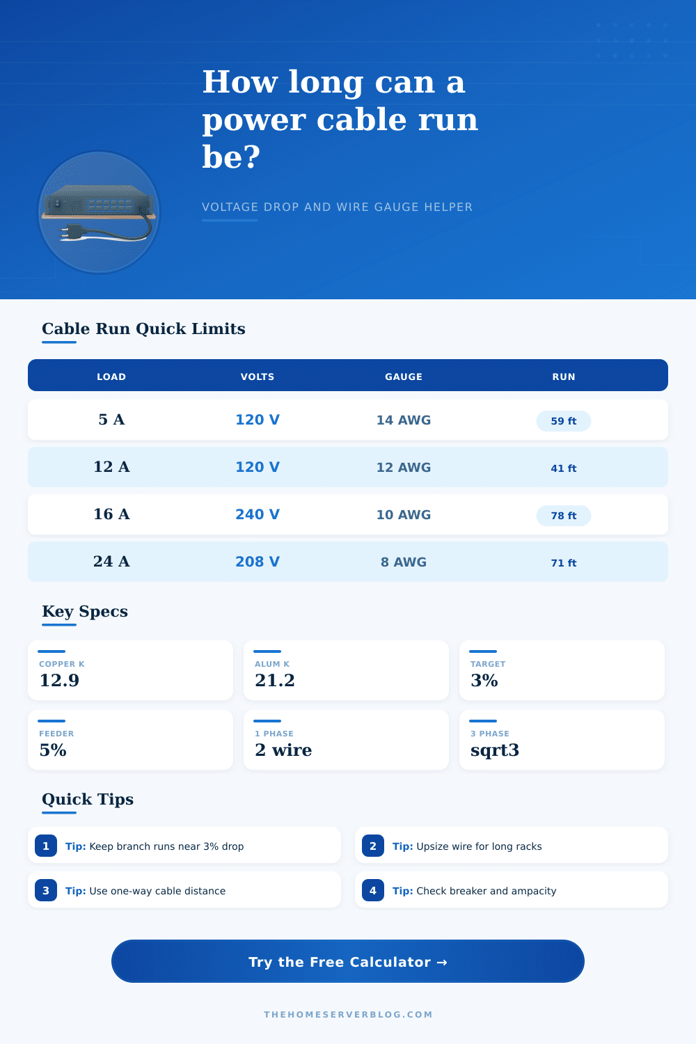
| NAS closet plus switch | 5A at 120V | 14 AWG copper | Often limited by receptacle layout |
| Half rack with UPS | 12A at 120V | 12 AWG copper | Good candidate for a dedicated circuit |
| GPU compute node | 16A at 240V | 10 AWG copper | Check continuous load derating |
| Three phase lab PDU | 24A at 208V | 8 AWG copper | Balance phases before final sizing |
💡Practical Tips
Voltage drop occur when electricity travels through a conductor. Voltage drop causes the voltage level at the end of a conductor to be less than the voltage levels at the beginning of that conductor. Voltage drop must be manage for the proper functioning of the electrical equipment.
For example, if the voltage requirements of an electrical server is 120 volt, delivering less than 120 volts to the server will result in the server not functioning correct. Voltage drop applies to 120-volt AC circuit, 48-volt DC circuits, and three phase circuits. The amount of voltage drop that occurs in a circuit is related to the length of the conductor, the amount of current that the electrical load will draw, and the material of the conductor.
What is Voltage Drop and How to Calculate It
To calculate the voltage drop that will occur along a circuit, you must enter the voltage, load current, one-way distance, conductor material, and wire gauge into a calculator. Each of these variables impact the resistance of the circuit. For instance, increasing the distance along the circuit will increase the resistance of the circuit.
Similarly, increasing the load on the circuit will increase the amount of current that moves through the circuit. Copper and aluminum has different resistivities, hence selecting the correct conductor material is important. Additionally, the phase configuration and power factor of the circuit will impact the voltage drop; single phase and DC circuits have a different voltage drop then three-phase circuits.
Single-phase and DC circuits use a multiplier of two in the calculation of voltage drop while three-phase circuits use the square root of three. Another setting within the calculator is the voltage drop percentage. This voltage can be any percentage relative to the supplied voltage, but typical percentage are 2% for sensitive electronics, 3% for standard branch circuits, and 5% for feeder circuits that supply other branch circuits.
This percentage allows electrical design professional to balance the performance requirements of the electrical equipment to the cost of providing the conductor. The calculator will provide information about the actual voltage drop that will result from the circuit plan that is entered, as well as the maximum distance that the conductor can run before the voltage drop reaches the percentage that is selected. This distance is helpful in determining whether or not there is enough room to place the conductor in the installation plan.
The distance measurements that are entered into the calculator should also be supplemented with a buffer to account for turns in the run of the conductor, drops into the racks that contain the electrical equipment, and to allow for loops in the conductor to permit for future maintenance of the circuits. A buffer of 10% or 15% of the entered distance will ensure that the calculated voltage drop is based upon the actual length of the conductor that will be installed. The results of the voltage drop calculation will show the delivered voltage to the electrical equipment; this delivered voltage must fall within the required voltage range of the equipment.
It is important to consider voltage drop relative to the ampacity of the circuit. These two parameter are independent of one another. For instance, it is possible that the ampacity of the conductor is sufficient to carry the load and the conductor is rated for the amount of current that will pass through it, but the voltage drop along that circuit may be too great due to the length of the conductor.
Conversely, low voltage drop indicate that the conductor is relatively short, but it may still have an ampacity limit due to high loads along the conductor. Both parameter should be considered before the circuits are energized. Additionally, the temperature of the terminals should also be considered; a conductor may be capable of high ampacities and low voltage drops at high temperatures but the terminals may be limited to much more lower temperatures.
This setting can also be entered into the calculator to ensure that the ampacity calculation is accurate relative to the electrical installation. The reference tables located on the page can help to determine the appropriate wire gauge prior to entering the voltage drop calculation. The formula table explain the multipliers for the different phase circuits and how the distance can be calculated as a result of the voltage drop.
Finally, the voltage drop calculator helps to show the relationship between the various variable in the circuit plan. For instance, if any of the variables related to increasing voltage drop are increased, the results of the calculation will indicate that high voltage drop can be avoided by using a larger wire gauge, reducing the length of the circuit run, or reducing the load current. Voltage drop occur when electricity travels through a conductor.
Voltage drop causes the voltage level at the end of a conductor to be less than the voltage levels at the beginning of that conductor. Voltage drop must be manage for the proper functioning of the electrical equipment. For example, if the voltage requirements of an electrical server is 120 volt, delivering less than 120 volts to the server will result in the server not functioning correct.
Voltage drop applies to 120-volt AC circuit, 48-volt DC circuits, and three phase circuits. The amount of voltage drop that occurs in a circuit is related to the length of the conductor, the amount of current that the electrical load will draw, and the material of the conductor. To calculate the voltage drop that will occur along a circuit, you must enter the voltage, load current, one-way distance, conductor material, and wire gauge into a calculator.
Each of these variables impact the resistance of the circuit. For instance, increasing the distance along the circuit will increase the resistance of the circuit. Similarly, increasing the load on the circuit will increase the amount of current that moves through the circuit.
Copper and aluminum has different resistivities, hence selecting the correct conductor material is important. Additionally, the phase configuration and power factor of the circuit will impact the voltage drop; single phase and DC circuits have a different voltage drop then three-phase circuits. Single-phase and DC circuits use a multiplier of two in the calculation of voltage drop while three-phase circuits use the square root of three.
Another setting within the calculator is the voltage drop percentage. This voltage can be any percentage relative to the supplied voltage, but typical percentage are 2% for sensitive electronics, 3% for standard branch circuits, and 5% for feeder circuits that supply other branch circuits. This percentage allows electrical design professional to balance the performance requirements of the electrical equipment to the cost of providing the conductor.
The calculator will provide information about the actual voltage drop that will result from the circuit plan that is entered, as well as the maximum distance that the conductor can run before the voltage drop reaches the percentage that is selected. This distance is helpful in determining whether or not there is enough room to place the conductor in the installation plan. The distance measurements that are entered into the calculator should also be supplemented with a buffer to account for turns in the run of the conductor, drops into the racks that contain the electrical equipment, and to allow for loops in the conductor to permit for future maintenance of the circuits.
A buffer of 10% or 15% of the entered distance will ensure that the calculated voltage drop is based upon the actual length of the conductor that will be installed. The results of the voltage drop calculation will show the delivered voltage to the electrical equipment; this delivered voltage must fall within the required voltage range of the equipment. It is important to consider voltage drop relative to the ampacity of the circuit.
These two parameter are independent of one another. For instance, it is possible that the ampacity of the conductor is sufficient to carry the load and the conductor is rated for the amount of current that will pass through it, but the voltage drop along that circuit may be too great due to the length of the conductor. Conversely, low voltage drop indicate that the conductor is relatively short, but it may still have an ampacity limit due to high loads along the conductor.
Both parameter should be considered before the circuits are energized. Additionally, the temperature of the terminals should also be considered; a conductor may be capable of high ampacities and low voltage drops at high temperatures but the terminals may be limited to much more lower temperatures. This setting can also be entered into the calculator to ensure that the ampacity calculation is accurate relative to the electrical installation.
The reference tables located on the page can help to determine the appropriate wire gauge prior to entering the voltage drop calculation. The formula table explain the multipliers for the different phase circuits and how the distance can be calculated as a result of the voltage drop. Finally, the voltage drop calculator helps to show the relationship between the various variable in the circuit plan.
For instance, if any of the variables related to increasing voltage drop are increased, the results of the calculation will indicate that high voltage drop can be avoided by using a larger wire gauge, reducing the length of the circuit run, or reducing the load current. Voltage drop occur when electricity travels through a conductor. Voltage drop causes the voltage level at the end of a conductor to be less than the voltage levels at the beginning of that conductor.
Voltage drop must be manage for the proper functioning of the electrical equipment. For example, if the voltage requirements of an electrical server is 120 volt, delivering less than 120 volts to the server will result in the server not functioning correct. Voltage drop applies to 120-volt AC circuit, 48-volt DC circuits, and three phase circuits.
The amount of voltage drop that occurs in a circuit is related to the length of the conductor, the amount of current that the electrical load will draw, and the material of the conductor. To calculate the voltage drop that will occur along a circuit, you must enter the voltage, load current, one-way distance, conductor material, and wire gauge into a calculator. Each of these variables impact the resistance of the circuit.
For instance, increasing the distance along the circuit will increase the resistance of the circuit. Similarly, increasing the load on the circuit will increase the amount of current that moves through the circuit. Copper and aluminum has different resistivities, hence selecting the correct conductor material is important.
Additionally, the phase configuration and power factor of the circuit will impact the voltage drop; single phase and DC circuits have a different voltage drop then three-phase circuits. Single-phase and DC circuits use a multiplier of two in the calculation of voltage drop while three-phase circuits use the square root of three. Another setting within the calculator is the voltage drop percentage.
This voltage can be any percentage relative to the supplied voltage, but typical percentage are 2% for sensitive electronics, 3% for standard branch circuits, and 5% for feeder circuits that supply other branch circuits. This percentage allows electrical design professional to balance the performance requirements of the electrical equipment to the cost of providing the conductor. The calculator will provide information about the actual voltage drop that will result from the circuit plan that is entered, as well as the maximum distance that the conductor can run before the voltage drop reaches the percentage that is selected.
This distance is helpful in determining whether or not there is enough room to place the conductor in the installation plan. The distance measurements that are entered into the calculator should also be supplemented with a buffer to account for turns in the run of the conductor, drops into the racks that contain the electrical equipment, and to allow for loops in the conductor to permit for future maintenance of the circuits. A buffer of 10% or 15% of the entered distance will ensure that the calculated voltage drop is based upon the actual length of the conductor that will be installed.
The results of the voltage drop calculation will show the delivered voltage to the electrical equipment; this delivered voltage must fall within the required voltage range of the equipment. It is important to consider voltage drop relative to the ampacity of the circuit. These two parameter are independent of one another.
For instance, it is possible that the ampacity of the conductor is sufficient to carry the load and the conductor is rated for the amount of current that will pass through it, but the voltage drop along that circuit may be too great due to the length of the conductor. Conversely, low voltage drop indicate that the conductor is relatively short, but it may still have an ampacity limit due to high loads along the conductor. Both parameter should be considered before the circuits are energized.
Additionally, the temperature of the terminals should also be considered; a conductor may be capable of high ampacities and low voltage drops at high temperatures but the terminals may be limited to much more lower temperatures. This setting can also be entered into the calculator to ensure that the ampacity calculation is accurate relative to the electrical installation. The reference tables located on the page can help to determine the appropriate wire gauge prior to entering the voltage drop calculation.
The formula table explain the multipliers for the different phase circuits and how the distance can be calculated as a result of the voltage drop. Finally, the voltage drop calculator helps to show the relationship between the various variable in the circuit plan. For instance, if any of the variables related to increasing voltage drop are increased, the results of the calculation will indicate that high voltage drop can be avoided by using a larger wire gauge, reducing the length of the circuit run, or reducing the load current.
Voltage drop occur when electricity travels through a conductor. Voltage drop causes the voltage level at the end of a conductor to be less than the voltage levels at the beginning of that conductor. Voltage drop must be manage for the proper functioning of the electrical equipment.
For example, if the voltage requirements of an electrical server is 120 volt, delivering less than 120 volts to the server will result in the server not functioning correct. Voltage drop applies to 120-volt AC circuit, 48-volt DC circuits, and three phase circuits. The amount of voltage drop that occurs in a circuit is related to the length of the conductor, the amount of current that the electrical load will draw, and the material of the conductor.
To calculate the voltage drop that will occur along a circuit, you must enter the voltage, load current, one-way distance, conductor material, and wire gauge into a calculator. Each of these variables impact the resistance of the circuit. For instance, increasing the distance along the circuit will increase the resistance of the circuit.
Similarly, increasing the load on the circuit will increase the amount of current that moves through the circuit. Copper and aluminum has different resistivities, hence selecting the correct conductor material is important. Additionally, the phase configuration and power factor of the circuit will impact the voltage drop; single phase and DC circuits have a different voltage drop then three-phase circuits.
Single-phase and DC circuits use a multiplier of two in the calculation of voltage drop while three-phase circuits use the square root of three. Another setting within the calculator is the voltage drop percentage. This voltage can be any percentage relative to the supplied voltage, but typical percentage are 2% for sensitive electronics, 3% for standard branch circuits, and 5% for feeder circuits that supply other branch circuits.
This percentage allows electrical design professional to balance the performance requirements of the electrical equipment to the cost of providing the conductor. The calculator will provide information about the actual voltage drop that will result from the circuit plan that is entered, as well as the maximum distance that the conductor can run before the voltage drop reaches the percentage that is selected. This distance is helpful in determining whether or not there is enough room to place the conductor in the installation plan.
The distance measurements that are entered into the calculator should also be supplemented with a buffer to account for turns in the run of the conductor, drops into the racks that contain the electrical equipment, and to allow for loops in the conductor to permit for future maintenance of the circuits. A buffer of 10% or 15% of the entered distance will ensure that the calculated voltage drop is based upon the actual length of the conductor that will be installed. The results of the voltage drop calculation will show the delivered voltage to the electrical equipment; this delivered voltage must fall within the required voltage range of the equipment.
It is important to consider voltage drop relative to the ampacity of the circuit. These two parameter are independent of one another. For instance, it is possible that the ampacity of the conductor is sufficient to carry the load and the conductor is rated for the amount of current that will pass through it, but the voltage drop along that circuit may be too great due to the length of the conductor.
Conversely, low voltage drop indicate that the conductor is relatively short, but it may still have an ampacity limit due to high loads along the conductor. Both parameter should be considered before the circuits are energized. Additionally, the temperature of the terminals should also be considered; a conductor may be capable of high ampacities and low voltage drops at high temperatures but the terminals may be limited to much more lower temperatures.
This setting can also be entered into the calculator to ensure that the ampacity calculation is accurate relative to the electrical installation. The reference tables located on the page can help to determine the appropriate wire gauge prior to entering the voltage drop calculation. The formula table explain the multipliers for the different phase circuits and how the distance can be calculated as a result of the voltage drop.
Finally, the voltage drop calculator helps to show the relationship between the various variable in the circuit plan. For instance, if any of the variables related to increasing voltage drop are increased, the results of the calculation will indicate that high voltage drop can be avoided by using a larger wire gauge, reducing the length of the circuit run, or reducing the load current. Voltage drop occur when electricity travels through a conductor.
Voltage drop causes the voltage level at the end of a conductor to be less than the voltage levels at the beginning of that conductor. Voltage drop must be manage for the proper functioning of the electrical equipment. For example, if the voltage requirements of an electrical server is 120 volt, delivering less than 120 volts to the server will result in the server not functioning correct.
Voltage drop applies to 120-volt AC circuit, 48-volt DC circuits, and three phase circuits. The amount of voltage drop that occurs in a circuit is related to the length of the conductor, the amount of current that the electrical load will draw, and the material of the conductor. To calculate the voltage drop that will occur along a circuit, you must enter the voltage, load current, one-way distance, conductor material, and wire gauge into a calculator.
Each of these variables impact the resistance of the circuit. For instance, increasing the distance along the circuit will increase the resistance of the circuit. Similarly, increasing the load on the circuit will increase the amount of current that moves through the circuit.
Copper and aluminum has different resistivities, hence selecting the correct conductor material is important. Additionally, the phase configuration and power factor of the circuit will impact the voltage drop; single phase and DC circuits have a different voltage drop then three-phase circuits. Single-phase and DC circuits use a multiplier of two in the calculation of voltage drop while three-phase circuits use the square root of three.
Another setting within the calculator is the voltage drop percentage. This voltage can be any percentage relative to the supplied voltage, but typical percentage are 2% for sensitive electronics, 3% for standard branch circuits, and 5% for feeder circuits that supply other branch circuits. This percentage allows electrical design professional to balance the performance requirements of the electrical equipment to the cost of providing the conductor.
The calculator will provide information about the actual voltage drop that will result from the circuit plan that is entered, as well as the maximum distance that the conductor can run before the voltage drop reaches the percentage that is selected. This distance is helpful in determining whether or not there is enough room to place the conductor in the installation plan. The distance measurements that are entered into the calculator should also be supplemented with a buffer to account for turns in the run of the conductor, drops into the racks that contain the electrical equipment, and to allow for loops in the conductor to permit for future maintenance of the circuits.
A buffer of 10% or 15% of the entered distance will ensure that the calculated voltage drop is based upon the actual length of the conductor that will be installed. The results of the voltage drop calculation will show the delivered voltage to the electrical equipment; this delivered voltage must fall within the required voltage range of the equipment. It is important to consider voltage drop relative to the ampacity of the circuit.
These two parameter are independent of one another. For instance, it is possible that the ampacity of the conductor is sufficient to carry the load and the conductor is rated for the amount of current that will pass through it, but the voltage drop along that circuit may be too great due to the length of the conductor. Conversely, low voltage drop indicate that the conductor is relatively short, but it may still have an ampacity limit due to high loads along the conductor.
Both parameter should be considered before the circuits are energized. Additionally, the temperature of the terminals should also be considered; a conductor may be capable of high ampacities and low voltage drops at high temperatures but the terminals may be limited to much more lower temperatures. This setting can also be entered into the calculator to ensure that the ampacity calculation is accurate relative to the electrical installation.
The reference tables located on the page can help to determine the appropriate wire gauge prior to entering the voltage drop calculation. The formula table explain the multipliers for the different phase circuits and how the distance can be calculated as a result of the voltage drop. Finally, the voltage drop calculator helps to show the relationship between the various variable in the circuit plan.
For instance, if any of the variables related to increasing voltage drop are increased, the results of the calculation will indicate that high voltage drop can be avoided by using a larger wire gauge, reducing the length of the circuit run, or reducing the load current. Voltage drop occur when electricity travels through a conductor. Voltage drop causes the voltage level at the end of a conductor to be less than the voltage levels at the beginning of that conductor.
Voltage drop must be manage for the proper functioning of the electrical equipment. For example, if the voltage requirements of an electrical server is 120 volt, delivering less than 120 volts to the server will result in the server not functioning correct. Voltage drop applies to 120-volt AC circuit, 48-volt DC circuits, and three phase circuits.
The amount of voltage drop that occurs in a circuit is related to the length of the conductor, the amount of current that the electrical load will draw, and the material of the conductor. To calculate the voltage drop that will occur along a circuit, you must enter the voltage, load current, one-way distance, conductor material, and wire gauge into a calculator. Each of these variables impact the resistance of the circuit.
For instance, increasing the distance along the circuit will increase the resistance of the circuit. Similarly, increasing the load on the circuit will increase the amount of current that moves through the circuit. Copper and aluminum has different resistivities, hence selecting the correct conductor material is important.
Additionally, the phase configuration and power factor of the circuit will impact the voltage drop; single phase and DC circuits have a different voltage drop then three-phase circuits. Single-phase and DC circuits use a multiplier of two in the calculation of voltage drop while three-phase circuits use the square root of three. Another setting within the calculator is the voltage drop percentage.
This voltage can be any percentage relative to the supplied voltage, but typical percentage are 2% for sensitive electronics, 3% for standard branch circuits, and 5% for feeder circuits that supply other branch circuits. This percentage allows electrical design professional to balance the performance requirements of the electrical equipment to the cost of providing the conductor. The calculator will provide information about the actual voltage drop that will result from the circuit plan that is entered, as well as the maximum distance that the conductor can run before the voltage drop reaches the percentage that is selected.
This distance is helpful in determining whether or not there is enough room to place the conductor in the installation plan. The distance measurements that are entered into the calculator should also be supplemented with a buffer to account for turns in the run of the conductor, drops into the racks that contain the electrical equipment, and to allow for loops in the conductor to permit for future maintenance of the circuits. A buffer of 10% or 15% of the entered distance will ensure that the calculated voltage drop is based upon the actual length of the conductor that will be installed.
The results of the voltage drop calculation will show the delivered voltage to the electrical equipment; this delivered voltage must fall within the required voltage range of the equipment. It is important to consider voltage drop relative to the ampacity of the circuit. These two parameter are independent of one another.
For instance, it is possible that the ampacity of the conductor is sufficient to carry the load and the conductor is rated for the amount of current that will pass through it, but the voltage drop along that circuit may be too great due to the length of the conductor. Conversely, low voltage drop indicate that the conductor is relatively short, but it may still have an ampacity limit due to high loads along the conductor. Both parameter should be considered before the circuits are energized.
Additionally, the temperature of the terminals should also be considered; a conductor may be capable of high ampacities and low voltage drops at high temperatures but the terminals may be limited to much more lower temperatures. This setting can also be entered into the calculator to ensure that the ampacity calculation is accurate relative to the electrical installation. The reference tables located on the page can help to determine the appropriate wire gauge prior to entering the voltage drop calculation.
The formula table explain the multipliers for the different phase circuits and how the distance can be calculated as a result of the voltage drop. Finally, the voltage drop calculator helps to show the relationship between the various variable in the circuit plan. For instance, if any of the variables related to increasing voltage drop are increased, the results of the calculation will indicate that high voltage drop can be avoided by using a larger wire gauge, reducing the length of the circuit run, or reducing the load current.
Voltage drop occur when electricity travels through a conductor. Voltage drop causes the voltage level at the end of a conductor to be less than the voltage levels at the beginning of that conductor. Voltage drop must be manage for the proper functioning of the electrical equipment.
For example, if the voltage requirements of an electrical server is 120 volt, delivering less than 120 volts to the server will result in the server not functioning correct. Voltage drop applies to 120-volt AC circuit, 48-volt DC circuits, and three phase circuits. The amount of voltage drop that occurs in a circuit is related to the length of the conductor, the amount of current that the electrical load will draw, and the material of the conductor.
To calculate the voltage drop that will occur along a circuit, you must enter the voltage, load current, one-way distance, conductor material, and wire gauge into a calculator. Each of these variables impact the resistance of the circuit. For instance, increasing the distance along the circuit will increase the resistance of the circuit.
Similarly, increasing the load on the circuit will increase the amount of current that moves through the circuit. Copper and aluminum has different resistivities, hence selecting the correct conductor material is important. Additionally, the phase configuration and power factor of the circuit will impact the voltage drop; single phase and DC circuits have a different voltage drop then three-phase circuits.
Single-phase and DC circuits use a multiplier of two in the calculation of voltage drop while three-phase circuits use the square root of three. Another setting within the calculator is the voltage drop percentage. This voltage can be any percentage relative to the supplied voltage, but typical percentage are 2% for sensitive electronics, 3% for standard branch circuits, and 5% for feeder circuits that supply other branch circuits.
This percentage allows electrical design professional to balance the performance requirements of the electrical equipment to the cost of providing the conductor. The calculator will provide information about the actual voltage drop that will result from the circuit plan that is entered, as well as the maximum distance that the conductor can run before the voltage drop reaches the percentage that is selected. This distance is helpful in determining whether or not there is enough room to place the conductor in the installation plan.
The distance measurements that are entered into the calculator should also be supplemented with a buffer to account for turns in the run of the conductor, drops into the racks that contain the electrical equipment, and to allow for loops in the conductor to permit for future maintenance of the circuits. A buffer of 10% or 15% of the entered distance will ensure that the calculated voltage drop is based upon the actual length of the conductor that will be installed. The results of the voltage drop calculation will show the delivered voltage to the electrical equipment; this delivered voltage must fall within the required voltage range of the equipment.
It is important to consider voltage drop relative to the ampacity of the circuit. These two parameter are independent of one another. For instance, it is possible that the ampacity of the conductor is sufficient to carry the load and the conductor is rated for the amount of current that will pass through it, but the voltage drop along that circuit may be too great due to the length of the conductor.
Conversely, low voltage drop indicate that the conductor is relatively short, but it may still have an ampacity limit due to high loads along the conductor. Both parameter should be considered before the circuits are energized. Additionally, the temperature of the terminals should also be considered; a conductor may be capable of high ampacities and low voltage drops at high temperatures but the terminals may be limited to much more lower temperatures.
This setting can also be entered into the calculator to ensure that the ampacity calculation is accurate relative to the electrical installation. The reference tables located on the page can help to determine the appropriate wire gauge prior to entering the voltage drop calculation. The formula table explain the multipliers for the different phase circuits and how the distance can be calculated as a result of the voltage drop.
Finally, the voltage drop calculator helps to show the relationship between the various variable in the circuit plan. For instance, if any of the variables related to increasing voltage drop are increased, the results of the calculation will indicate that high voltage drop can be avoided by using a larger wire gauge, reducing the length of the circuit run, or reducing the load current. Voltage drop occur when electricity travels through a conductor.
Voltage drop causes the voltage level at the end of a conductor to be less than the voltage levels at the beginning of that conductor. Voltage drop must be manage for the proper functioning of the electrical equipment. For example, if the voltage requirements of an electrical server is 120 volt, delivering less than 120 volts to the server will result in the server not functioning correct.
Voltage drop applies to 120-volt AC circuit, 48-volt DC circuits, and three phase circuits. The amount of voltage drop that occurs in a circuit is related to the length of the conductor, the amount of current that the electrical load will draw, and the material of the conductor. To calculate the voltage drop that will occur along a circuit, you must enter the voltage, load current, one-way distance, conductor material, and wire gauge into a calculator.
Each of these variables impact the resistance of the circuit. For instance, increasing the distance along the circuit will increase the resistance of the circuit. Similarly, increasing the load on the circuit will increase the amount of current that moves through the circuit.
Copper and aluminum has different resistivities, hence selecting the correct conductor material is important. Additionally, the phase configuration and power factor of the circuit will impact the voltage drop; single phase and DC circuits have a different voltage drop then three-phase circuits. Single-phase and DC circuits use a multiplier of two in the calculation of voltage drop while three-phase circuits use the square root of three.
Another setting within the calculator is the voltage drop percentage. This voltage can be any percentage relative to the supplied voltage, but typical percentage are 2% for sensitive electronics, 3% for standard branch circuits, and 5% for feeder circuits that supply other branch circuits. This percentage allows electrical design professional to balance the performance requirements of the electrical equipment to the cost of providing the conductor.
The calculator will provide information about the actual voltage drop that will result from the circuit plan that is entered, as well as the maximum distance that the conductor can run before the voltage drop reaches the percentage that is selected. This distance is helpful in determining whether or not there is enough room to place the conductor in the installation plan. The distance measurements that are entered into the calculator should also be supplemented with a buffer to account for turns in the run of the conductor, drops into the racks that contain the electrical equipment, and to allow for loops in the conductor to permit for future maintenance of the circuits.
A buffer of 10% or 15% of the entered distance will ensure that the calculated voltage drop is based upon the actual length of the conductor that will be installed. The results of the voltage drop calculation will show the delivered voltage to the electrical equipment; this delivered voltage must fall within the required voltage range of the equipment. It is important to consider voltage drop relative to the ampacity of the circuit.
These two parameter are independent of one another. For instance, it is possible that the ampacity of the conductor is sufficient to carry the load and the conductor is rated for the amount of current that will pass through it, but the voltage drop along that circuit may be too great due to the length of the conductor. Conversely, low voltage drop indicate that the conductor is relatively short, but it may still have an ampacity limit due to high loads along the conductor.
Both parameter should be considered before the circuits are energized. Additionally, the temperature of the terminals should also be considered; a conductor may be capable of high ampacities and low voltage drops at high temperatures but the terminals may be limited to much more lower temperatures. This setting can also be entered into the calculator to ensure that the ampacity calculation is accurate relative to the electrical installation.
The reference tables located on the page can help to determine the appropriate wire gauge prior to entering the voltage drop calculation. The formula table explain the multipliers for the different phase circuits and how the distance can be calculated as a result of the voltage drop. Finally, the voltage drop calculator helps to show the relationship between the various variable in the circuit plan.
For instance, if any of the variables related to increasing voltage drop are increased, the results of the calculation will indicate that high voltage drop can be avoided by using a larger wire gauge, reducing the length of the circuit run, or reducing the load current. Voltage drop occur when electricity travels through a conductor. Voltage drop causes the voltage level at the end of a conductor to be less than the voltage levels at the beginning of that conductor.
Voltage drop must be manage for the proper functioning of the electrical equipment. For example, if the voltage requirements of an electrical server is 120 volt, delivering less than 120 volts to the server will result in the server not functioning correct. Voltage drop applies to 120-volt AC circuit, 48-volt DC circuits, and three phase circuits.
The amount of voltage drop that occurs in a circuit is related to the length of the conductor, the amount of current that the electrical load will draw, and the material of the conductor. To calculate the voltage drop that will occur along a circuit, you must enter the voltage, load current, one-way distance, conductor material, and wire gauge into a calculator. Each of these variables impact the resistance of the circuit.
For instance, increasing the distance along the circuit will increase the resistance of the circuit. Similarly, increasing the load on the circuit will increase the amount of current that moves through the circuit. Copper and aluminum has different resistivities, hence selecting the correct conductor material is important.
Additionally, the phase configuration and power factor of the circuit will impact the voltage drop; single phase and DC circuits have a different voltage drop then three-phase circuits. Single-phase and DC circuits use a multiplier of two in the calculation of voltage drop while three-phase circuits use the square root of three. Another setting within the calculator is the voltage drop percentage.
This voltage can be any percentage relative to the supplied voltage, but typical percentage are 2% for sensitive electronics, 3% for standard branch circuits, and 5% for feeder circuits that supply other branch circuits. This percentage allows electrical design professional to balance the performance requirements of the electrical equipment to the cost of providing the conductor. The calculator will provide information about the actual voltage drop that will result from the circuit plan that is entered, as well as the maximum distance that the conductor can run before the voltage drop reaches the percentage that is selected.
This distance is helpful in determining whether or not there is enough room to place the conductor in the installation plan. The distance measurements that are entered into the calculator should also be supplemented with a buffer to account for turns in the run of the conductor, drops into the racks that contain the electrical equipment, and to allow for loops in the conductor to permit for future maintenance of the circuits. A buffer of 10% or 15% of the entered distance will ensure that the calculated voltage drop is based upon the actual length of the conductor that will be installed.
The results of the voltage drop calculation will show the delivered voltage to the electrical equipment; this delivered voltage must fall within the required voltage range of the equipment. It is important to consider voltage drop relative to the ampacity of the circuit. These two parameter are independent of one another.
For instance, it is possible that the ampacity of the conductor is sufficient to carry the load and the conductor is rated for the amount of current that will pass through it, but the voltage drop along that circuit may be too great due to the length of the conductor. Conversely, low voltage drop indicate that the conductor is relatively short, but it may still have an ampacity limit due to high loads along the conductor. Both parameter should be considered before the circuits are energized.
Additionally, the temperature of the terminals should also be considered; a conductor may be capable of high ampacities and low voltage drops at high temperatures but the terminals may be limited to much more lower temperatures. This setting can also be entered into the calculator to ensure that the ampacity calculation is accurate relative to the electrical installation. The reference tables located on the page can help to determine the appropriate wire gauge prior to entering the voltage drop calculation.
The formula table explain the multipliers for the different phase circuits and how the distance can be calculated as a result of the voltage drop. Finally, the voltage drop calculator helps to show the relationship between the various variable in the circuit plan. For instance, if any of the variables related to increasing voltage drop are increased, the results of the calculation will indicate that high voltage drop can be avoided by using a larger wire gauge, reducing the length of the circuit run, or reducing the load current.
Voltage drop occur when electricity travels through a conductor. Voltage drop causes the voltage level at the end of a conductor to be less than the voltage levels at the beginning of that conductor. Voltage drop must be manage for the proper functioning of the electrical equipment.
For example, if the voltage requirements of an electrical server is 120 volt, delivering less than 120 volts to the server will result in the server not functioning correct. Voltage drop applies to 120-volt AC circuit, 48-volt DC circuits, and three phase circuits. The amount of voltage drop that occurs in a circuit is related to the length of the conductor, the amount of current that the electrical load will draw, and the material of the conductor.
To calculate the voltage drop that will occur along a circuit, you must enter the voltage, load current, one-way distance, conductor material, and wire gauge into a calculator. Each of these variables impact the resistance of the circuit. For instance, increasing the distance along the circuit will increase the resistance of the circuit.
Similarly, increasing the load on the circuit will increase the amount of current that moves through the circuit. Copper and aluminum has different resistivities, hence selecting the correct conductor material is important. Additionally, the phase configuration and power factor of the circuit will impact the voltage drop; single phase and DC circuits have a different voltage drop then three-phase circuits.
Single-phase and DC circuits use a multiplier of two in the calculation of voltage drop while three-phase circuits use the square root of three. Another setting within the calculator is the voltage drop percentage. This voltage can be any percentage relative to the supplied voltage, but typical percentage are 2% for sensitive electronics, 3% for standard branch circuits, and 5% for feeder circuits that supply other branch circuits.
This percentage allows electrical design professional to balance the performance requirements of the electrical equipment to the cost of providing the conductor. The calculator will provide information about the actual voltage drop that will result from the circuit plan that is entered, as well as the maximum distance that the conductor can run before the voltage drop reaches the percentage that is selected. This distance is helpful in determining whether or not there is enough room to place the conductor in the installation plan.
The distance measurements that are entered into the calculator should also be supplemented with a buffer to account for turns in the run of the conductor, drops into the racks that contain the electrical equipment, and to allow for loops in the conductor to permit for future maintenance of the circuits. A buffer of 10% or 15% of the entered distance will ensure that the calculated voltage drop is based upon the actual length of the conductor that will be installed. The results of the voltage drop calculation will show the delivered voltage to the electrical equipment; this delivered voltage must fall within the required voltage range of the equipment.
It is important to consider voltage drop relative to the ampacity of the circuit. These two parameter are independent of one another. For instance, it is possible that the ampacity of the conductor is sufficient to carry the load and the conductor is rated for the amount of current that will pass through it, but the voltage drop along that circuit may be too great due to the length of the conductor.
Conversely, low voltage drop indicate that the conductor is relatively short, but it may still have an ampacity limit due to high loads along the conductor. Both parameter should be considered before the circuits are energized. Additionally, the temperature of the terminals should also be considered; a conductor may be capable of high ampacities and low voltage drops at high temperatures but the terminals may be limited to much more lower temperatures.
This setting can also be entered into the calculator to ensure that the ampacity calculation is accurate relative to the electrical installation. The reference tables located on the page can help to determine the appropriate wire gauge prior to entering the voltage drop calculation. The formula table explain the multipliers for the different phase circuits and how the distance can be calculated as a result of the voltage drop.
Finally, the voltage drop calculator helps to show the relationship between the various variable in the circuit plan. For instance, if any of the variables related to increasing voltage drop are increased, the results of the calculation will indicate that high voltage drop can be avoided by using a larger wire gauge, reducing the length of the circuit run, or reducing the load current. Voltage drop occur when electricity travels through a conductor.
Voltage drop causes the voltage level at the end of a conductor to be less than the voltage levels at the beginning of that conductor. Voltage drop must be manage for the proper functioning of the electrical equipment. For example, if the voltage requirements of an electrical server is 120 volt, delivering less than 120 volts to the server will result in the server not functioning correct.
Voltage drop applies to 120-volt AC circuit, 48-volt DC circuits, and three phase circuits. The amount of voltage drop that occurs in a circuit is related to the length of the conductor, the amount of current that the electrical load will draw, and the material of the conductor. To calculate the voltage drop that will occur along a circuit, you must enter the voltage, load current, one-way distance, conductor material, and wire gauge into a calculator.
Each of these variables impact the resistance of the circuit. For instance, increasing the distance along the circuit will increase the resistance of the circuit. Similarly, increasing the load on the circuit will increase the amount of current that moves through the circuit.
Copper and aluminum has different resistivities, hence selecting the correct conductor material is important. Additionally, the phase configuration and power factor of the circuit will impact the voltage drop; single phase and DC circuits have a different voltage drop then three-phase circuits. Single-phase and DC circuits use a multiplier of two in the calculation of voltage drop while three-phase circuits use the square root of three.
Another setting within the calculator is the voltage drop percentage. This voltage can be any percentage relative to the supplied voltage, but typical percentage are 2% for sensitive electronics, 3% for standard branch circuits, and 5% for feeder circuits that supply other branch circuits. This percentage allows electrical design professional to balance the performance requirements of the electrical equipment to the cost of providing the conductor.
The calculator will provide information about the actual voltage drop that will result from the circuit plan that is entered, as well as the maximum distance that the conductor can run before the voltage drop reaches the percentage that is selected. This distance is helpful in determining whether or not there is enough room to place the conductor in the installation plan. The distance measurements that are entered into the calculator should also be supplemented with a buffer to account for turns in the run of the conductor, drops into the racks that contain the electrical equipment, and to allow for loops in the conductor to permit for future maintenance of the circuits.
A buffer of 10% or 15% of the entered distance will ensure that the calculated voltage drop is based upon the actual length of the conductor that will be installed. The results of the voltage drop calculation will show the delivered voltage to the electrical equipment; this delivered voltage must fall within the required voltage range of the equipment. It is important to consider voltage drop relative to the ampacity of the circuit.
These two parameter are independent of one another. For instance, it is possible that the ampacity of the conductor is sufficient to carry the load and the conductor is rated for the amount of current that will pass through it, but the voltage drop along that circuit may be too great due to the length of the conductor. Conversely, low voltage drop indicate that the conductor is relatively short, but it may still have an ampacity limit due to high loads along the conductor.
Both parameter should be considered before the circuits are energized. Additionally, the temperature of the terminals should also be considered; a conductor may be capable of high ampacities and low voltage drops at high temperatures but the terminals may be limited to much more lower temperatures. This setting can also be entered into the calculator to ensure that the ampacity calculation is accurate relative to the electrical installation.
The reference tables located on the page can help to determine the appropriate wire gauge prior to entering the voltage drop calculation. The formula table explain the multipliers for the different phase circuits and how the distance can be calculated as a result of the voltage drop. Finally, the voltage drop calculator helps to show the relationship between the various variable in the circuit plan.
For instance, if any of the variables related to increasing voltage drop are increased, the results of the calculation will indicate that high voltage drop can be avoided by using a larger wire gauge, reducing the length of the circuit run, or reducing the load current. Voltage drop occur when electricity travels through a conductor. Voltage drop causes the voltage level at the end of a conductor to be less than the voltage levels at the beginning of that conductor.
Voltage drop must be manage for the proper functioning of the electrical equipment. For example, if the voltage requirements of an electrical server is 120 volt, delivering less than 120 volts to the server will result in the server not functioning correct. Voltage drop applies to 120-volt AC circuit, 48-volt DC circuits, and three phase circuits.
The amount of voltage drop that occurs in a circuit is related to the length of the conductor, the amount of current that the electrical load will draw, and the material of the conductor. To calculate the voltage drop that will occur along a circuit, you must enter the voltage, load current, one-way distance, conductor material, and wire gauge into a calculator. Each of these variables impact the resistance of the circuit.
For instance, increasing the distance along the circuit will increase the resistance of the circuit. Similarly, increasing the load on the circuit will increase the amount of current that moves through the circuit. Copper and aluminum has different resistivities, hence selecting the correct conductor material is important.
Additionally, the phase configuration and power factor of the circuit will impact the voltage drop; single phase and DC circuits have a different voltage drop then three-phase circuits. Single-phase and DC circuits use a multiplier of two in the calculation of voltage drop while three-phase circuits use the square root of three. Another setting within the calculator is the voltage drop percentage.
This voltage can be any percentage relative to the supplied voltage, but typical percentage are 2% for sensitive electronics, 3% for standard branch circuits, and 5% for feeder circuits that supply other branch circuits. This percentage allows electrical design professional to balance the performance requirements of the electrical equipment to the cost of providing the conductor. The calculator will provide information about the actual voltage drop that will result from the circuit plan that is entered, as well as the maximum distance that the conductor can run before the voltage drop reaches the percentage that is selected.
This distance is helpful in determining whether or not there is enough room to place the conductor in the installation plan. The distance measurements that are entered into the calculator should also be supplemented with a buffer to account for turns in the run of the conductor, drops into the racks that contain the electrical equipment, and to allow for loops in the conductor to permit for future maintenance of the circuits. A buffer of 10% or 15% of the entered distance will ensure that the calculated voltage drop is based upon the actual length of the conductor that will be installed.
The results of the voltage drop calculation will show the delivered voltage to the electrical equipment; this delivered voltage must fall within the required voltage range of the equipment. It is important to consider voltage drop relative to the ampacity of the circuit. These two parameter are independent of one another.
For instance, it is possible that the ampacity of the conductor is sufficient to carry the load and the conductor is rated for the amount of current that will pass through it, but the voltage drop along that circuit may be too great due to the length of the conductor. Conversely, low voltage drop indicate that the conductor is relatively short, but it may still have an ampacity limit due to high loads along the conductor. Both parameter should be considered before the circuits are energized.
Additionally, the temperature of the terminals should also be considered; a conductor may be capable of high ampacities and low voltage drops at high temperatures but the terminals may be limited to much more lower temperatures. This setting can also be entered into the calculator to ensure that the ampacity calculation is accurate relative to the electrical installation. The reference tables located on the page can help to determine the appropriate wire gauge prior to entering the voltage drop calculation.
The formula table explain the multipliers for the different phase circuits and how the distance can be calculated as a result of the voltage drop. Finally, the voltage drop calculator helps to show the relationship between the various variable in the circuit plan. For instance, if any of the variables related to increasing voltage drop are increased, the results of the calculation will indicate that high voltage drop can be avoided by using a larger wire gauge, reducing the length of the circuit run, or reducing the load current.
Voltage drop occur when electricity travels through a conductor. Voltage drop causes the voltage level at the end of a conductor to be less than the voltage levels at the beginning of that conductor. Voltage drop must be manage for the proper functioning of the electrical equipment.
For example, if the voltage requirements of an electrical server is 120 volt, delivering less than 120 volts to the server will result in the server not functioning correct. Voltage drop applies to 120-volt AC circuit, 48-volt DC circuits, and three phase circuits. The amount of voltage drop that occurs in a circuit is related to the length of the conductor, the amount of current that the electrical load will draw, and the material of the conductor.
To calculate the voltage drop that will occur along a circuit, you must enter the voltage, load current, one-way distance, conductor material, and wire gauge into a calculator. Each of these variables impact the resistance of the circuit. For instance, increasing the distance along the circuit will increase the resistance of the circuit.
Similarly, increasing the load on the circuit will increase the amount of current that moves through the circuit. Copper and aluminum has different resistivities, hence selecting the correct conductor material is important. Additionally, the phase configuration and power factor of the circuit will impact the voltage drop; single phase and DC circuits have a different voltage drop then three-phase circuits.
Single-phase and DC circuits use a multiplier of two in the calculation of voltage drop while three-phase circuits use the square root of three. Another setting within the calculator is the voltage drop percentage. This voltage can be any percentage relative to the supplied voltage, but typical percentage are 2% for sensitive electronics, 3% for standard branch circuits, and 5% for feeder circuits that supply other branch circuits.
This percentage allows electrical design professional to balance the performance requirements of the electrical equipment to the cost of providing the conductor. The calculator will provide information about the actual voltage drop that will result from the circuit plan that is entered, as well as the maximum distance that the conductor can run before the voltage drop reaches the percentage that is selected. This distance is helpful in determining whether or not there is enough room to place the conductor in the installation plan.
The distance measurements that are entered into the calculator should also be supplemented with a buffer to account for turns in the run of the conductor, drops into the racks that contain the electrical equipment, and to allow for loops in the conductor to permit for future maintenance of the circuits. A buffer of 10% or 15% of the entered distance will ensure that the calculated voltage drop is based upon the actual length of the conductor that will be installed. The results of the voltage drop calculation will show the delivered voltage to the electrical equipment; this delivered voltage must fall within the required voltage range of the equipment.
It is important to consider voltage drop relative to the ampacity of the circuit. These two parameter are independent of one another. For instance, it is possible that the ampacity of the conductor is sufficient to carry the load and the conductor is rated for the amount of current that will pass through it, but the voltage drop along that circuit may be too great due to the length of the conductor.
Conversely, low voltage drop indicate that the conductor is relatively short, but it may still have an ampacity limit due to high loads along the conductor. Both parameter should be considered before the circuits are energized. Additionally, the temperature of the terminals should also be considered; a conductor may be capable of high ampacities and low voltage drops at high temperatures but the terminals may be limited to much more lower temperatures.
This setting can also be entered into the calculator to ensure that the ampacity calculation is accurate relative to the electrical installation. The reference tables located on the page can help to determine the appropriate wire gauge prior to entering the voltage drop calculation. The formula table explain the multipliers for the different phase circuits and how the distance can be calculated as a result of the voltage drop.
Finally, the voltage drop calculator helps to show the relationship between the various variable in the circuit plan. For instance, if any of the variables related to increasing voltage drop are increased, the results of the calculation will indicate that high voltage drop can be avoided by using a larger wire gauge, reducing the length of the circuit run, or reducing the load current. Voltage drop occur when electricity travels through a conductor.
Voltage drop causes the voltage level at the end of a conductor to be less than the voltage levels at the beginning of that conductor. Voltage drop must be manage for the proper functioning of the electrical equipment. For example, if the voltage requirements of an electrical server is 120 volt, delivering less than 120 volts to the server will result in the server not functioning correct.
Voltage drop applies to 120-volt AC circuit, 48-volt DC circuits, and three phase circuits. The amount of voltage drop that occurs in a circuit is related to the length of the conductor, the amount of current that the electrical load will draw, and the material of the conductor. To calculate the voltage drop that will occur along a circuit, you must enter the voltage, load current, one-way distance, conductor material, and wire gauge into a calculator.
Each of these variables impact the resistance of the circuit. For instance, increasing the distance along the circuit will increase the resistance of the circuit. Similarly, increasing the load on the circuit will increase the amount of current that moves through the circuit.
Copper and aluminum has different resistivities, hence selecting the correct conductor material is important. Additionally, the phase configuration and power factor of the circuit will impact the voltage drop; single phase and DC circuits have a different voltage drop then three-phase circuits. Single-phase and DC circuits use a multiplier of two in the calculation of voltage drop while three-phase circuits use the square root of three.
Another setting within the calculator is the voltage drop percentage. This voltage can be any percentage relative to the supplied voltage, but typical percentage are 2% for sensitive electronics, 3% for standard branch circuits, and 5% for feeder circuits that supply other branch circuits. This percentage allows electrical design professional to balance the performance requirements of the electrical equipment to the cost of providing the conductor.
The calculator will provide information about the actual voltage drop that will result from the circuit plan that is entered, as well as the maximum distance that the conductor can run before the voltage drop reaches the percentage that is selected. This distance is helpful in determining whether or not there is enough room to place the conductor in the installation plan. The distance measurements that are entered into the calculator should also be supplemented with a buffer to account for turns in the run of the conductor, drops into the racks that contain the electrical equipment, and to allow for loops in the conductor to permit for future maintenance of the circuits.
A buffer of 10% or 15% of the entered distance will ensure that the calculated voltage drop is based upon the actual length of the conductor that will be installed. The results of the voltage drop calculation will show the delivered voltage to the electrical equipment; this delivered voltage must fall within the required voltage range of the equipment. It is important to consider voltage drop relative to the ampacity of the circuit.
These two parameter are independent of one another. For instance, it is possible that the ampacity of the conductor is sufficient to carry the load and the conductor is rated for the amount of current that will pass through it, but the voltage drop along that circuit may be too great due to the length of the conductor. Conversely, low voltage drop indicate that the conductor is relatively short, but it may still have an ampacity limit due to high loads along the conductor.
Both parameter should be considered before the circuits are energized. Additionally, the temperature of the terminals should also be considered; a conductor may be capable of high ampacities and low voltage drops at high temperatures but the terminals may be limited to much more lower temperatures. This setting can also be entered into the calculator to ensure that the ampacity calculation is accurate relative to the electrical installation.
The reference tables located on the page can help to determine the appropriate wire gauge prior to entering the voltage drop calculation. The formula table explain the multipliers for the different phase circuits and how the distance can be calculated as a result of the voltage drop. Finally, the voltage drop calculator helps to show the relationship between the various variable in the circuit plan.
For instance, if any of the variables related to increasing voltage drop are increased, the results of the calculation will indicate that high voltage drop can be avoided by using a larger wire gauge, reducing the length of the circuit run, or reducing the load current. Voltage drop occur when electricity travels through a conductor. Voltage drop causes the voltage level at the end of a conductor to be less than the voltage levels at the beginning of that conductor.
Voltage drop must be manage for the proper functioning of the electrical equipment. For example, if the voltage requirements of an electrical server is 120 volt, delivering less than 120 volts to the server will result in the server not functioning correct. Voltage drop applies to 120-volt AC circuit, 48-volt DC circuits, and three phase circuits.
The amount of voltage drop that occurs in a circuit is related to the length of the conductor, the amount of current that the electrical load will draw, and the material of the conductor. To calculate the voltage drop that will occur along a circuit, you must enter the voltage, load current, one-way distance, conductor material, and wire gauge into a calculator. Each of these variables impact the resistance of the circuit.
For instance, increasing the distance along the circuit will increase the resistance of the circuit. Similarly, increasing the load on the circuit will increase the amount of current that moves through the circuit. Copper and aluminum has different resistivities, hence selecting the correct conductor material is important.
Additionally, the phase configuration and power factor of the circuit will impact the voltage drop; single phase and DC circuits have a different voltage drop then three-phase circuits. Single-phase and DC circuits use a multiplier of two in the calculation of voltage drop while three-phase circuits use the square root of three. Another setting within the calculator is the voltage drop percentage.
This voltage can be any percentage relative to the supplied voltage, but typical percentage are 2% for sensitive electronics, 3% for standard branch circuits, and 5% for feeder circuits that supply other branch circuits. This percentage allows electrical design professional to balance the performance requirements of the electrical equipment to the cost of providing the conductor. The calculator will provide information about the actual voltage drop that will result from the circuit plan that is entered, as well as the maximum distance that the conductor can run before the voltage drop reaches the percentage that is selected.
This distance is helpful in determining whether or not there is enough room to place the conductor in the installation plan. The distance measurements that are entered into the calculator should also be supplemented with a buffer to account for turns in the run of the conductor, drops into the racks that contain the electrical equipment, and to allow for loops in the conductor to permit for future maintenance of the circuits. A buffer of 10% or 15% of the entered distance will ensure that the calculated voltage drop is based upon the actual length of the conductor that will be installed.
The results of the voltage drop calculation will show the delivered voltage to the electrical equipment; this delivered voltage must fall within the required voltage range of the equipment. It is important to consider voltage drop relative to the ampacity of the circuit. These two parameter are independent of one another.
For instance, it is possible that the ampacity of the conductor is sufficient to carry the load and the conductor is rated for the amount of current that will pass through it, but the voltage drop along that circuit may be too great due to the length of the conductor. Conversely, low voltage drop indicate that the conductor is relatively short, but it may still have an ampacity limit due to high loads along the conductor. Both parameter should be considered before the circuits are energized.
Additionally, the temperature of the terminals should also be considered; a conductor may be capable of high ampacities and low voltage drops at high temperatures but the terminals may be limited to much more lower temperatures. This setting can also be entered into the calculator to ensure that the ampacity calculation is accurate relative to the electrical installation. The reference tables located on the page can help to determine the appropriate wire gauge prior to entering the voltage drop calculation.
The formula table explain the multipliers for the different phase circuits and how the distance can be calculated as a result of the voltage drop. Finally, the voltage drop calculator helps to show the relationship between the various variable in the circuit plan. For instance, if any of the variables related to increasing voltage drop are increased, the results of the calculation will indicate that high voltage drop can be avoided by using a larger wire gauge, reducing the length of the circuit run, or reducing the load current.
Voltage drop occur when electricity travels through a conductor. Voltage drop causes the voltage level at the end of a conductor to be less than the voltage levels at the beginning of that conductor. Voltage drop must be manage for the proper functioning of the electrical equipment.
For example, if the voltage requirements of an electrical server is 120 volt, delivering less than 120 volts to the server will result in the server not functioning correct. Voltage drop applies to 120-volt AC circuit, 48-volt DC circuits, and three phase circuits. The amount of voltage drop that occurs in a circuit is related to the length of the conductor, the amount of current that the electrical load will draw, and the material of the conductor.
To calculate the voltage drop that will occur along a circuit, you must enter the voltage, load current, one-way distance, conductor material, and wire gauge into a calculator. Each of these variables impact the resistance of the circuit. For instance, increasing the distance along the circuit will increase the resistance of the circuit.
Similarly, increasing the load on the circuit will increase the amount of current that moves through the circuit. Copper and aluminum has different resistivities, hence selecting the correct conductor material is important. Additionally, the phase configuration and power factor of the circuit will impact the voltage drop; single phase and DC circuits have a different voltage drop then three-phase circuits.
Single-phase and DC circuits use a multiplier of two in the calculation of voltage drop while three-phase circuits use the square root of three. Another setting within the calculator is the voltage drop percentage. This voltage can be any percentage relative to the supplied voltage, but typical percentage are 2% for sensitive electronics, 3% for standard branch circuits, and 5% for feeder circuits that supply other branch circuits.
This percentage allows electrical design professional to balance the performance requirements of the electrical equipment to the cost of providing the conductor. The calculator will provide information about the actual voltage drop that will result from the circuit plan that is entered, as well as the maximum distance that the conductor can run before the voltage drop reaches the percentage that is selected. This distance is helpful in determining whether or not there is enough room to place the conductor in the installation plan.
The distance measurements that are entered into the calculator should also be supplemented with a buffer to account for turns in the run of the conductor, drops into the racks that contain the electrical equipment, and to allow for loops in the conductor to permit for future maintenance of the circuits. A buffer of 10% or 15% of the entered distance will ensure that the calculated voltage drop is based upon the actual length of the conductor that will be installed. The results of the voltage drop calculation will show the delivered voltage to the electrical equipment; this delivered voltage must fall within the required voltage range of the equipment.
It is important to consider voltage drop relative to the ampacity of the circuit. These two parameter are independent of one another. For instance, it is possible that the ampacity of the conductor is sufficient to carry the load and the conductor is rated for the amount of current that will pass through it, but the voltage drop along that circuit may be too great due to the length of the conductor.
Conversely, low voltage drop indicate that the conductor is relatively short, but it may still have an ampacity limit due to high loads along the conductor. Both parameter should be considered before the circuits are energized. Additionally, the temperature of the terminals should also be considered; a conductor may be capable of high ampacities and low voltage drops at high temperatures but the terminals may be limited to much more lower temperatures.
This setting can also be entered into the calculator to ensure that the ampacity calculation is accurate relative to the electrical installation. The reference tables located on the page can help to determine the appropriate wire gauge prior to entering the voltage drop calculation. The formula table explain the multipliers for the different phase circuits and how the distance can be calculated as a result of the voltage drop.
Finally, the voltage drop calculator helps to show the relationship between the various variable in the circuit plan. For instance, if any of the variables related to increasing voltage drop are increased, the results of the calculation will indicate that high voltage drop can be avoided by using a larger wire gauge, reducing the length of the circuit run, or reducing the load current. Voltage drop occur when electricity travels through a conductor.
Voltage drop causes the voltage level at the end of a conductor to be less than the voltage levels at the beginning of that conductor. Voltage drop must be manage for the proper functioning of the electrical equipment. For example, if the voltage requirements of an electrical server is 120 volt, delivering less than 120 volts to the server will result in the server not functioning correct.
Voltage drop applies to 120-volt AC circuit, 48-volt DC circuits, and three phase circuits. The amount of voltage drop that occurs in a circuit is related to the length of the conductor, the amount of current that the electrical load will draw, and the material of the conductor. To calculate the voltage drop that will occur along a circuit, you must enter the voltage, load current, one-way distance, conductor material, and wire gauge into a calculator.
Each of these variables impact the resistance of the circuit. For instance, increasing the distance along the circuit will increase the resistance of the circuit. Similarly, increasing the load on the circuit will increase the amount of current that moves through the circuit.
Copper and aluminum has different resistivities, hence selecting the correct conductor material is important. Additionally, the phase configuration and power factor of the circuit will impact the voltage drop; single phase and DC circuits have a different voltage drop then three-phase circuits. Single-phase and DC circuits use a multiplier of two in the calculation of voltage drop while three-phase circuits use the square root of three.
Another setting within the calculator is the voltage drop percentage. This voltage can be any percentage relative to the supplied voltage, but typical percentage are 2% for sensitive electronics, 3% for standard branch circuits, and 5% for feeder circuits that supply other branch circuits. This percentage allows electrical design professional to balance the performance requirements of the electrical equipment to the cost of providing the conductor.
The calculator will provide information about the actual voltage drop that will result from the circuit plan that is entered, as well as the maximum distance that the conductor can run before the voltage drop reaches the percentage that is selected. This distance is helpful in determining whether or not there is enough room to place the conductor in the installation plan. The distance measurements that are entered into the calculator should also be supplemented with a buffer to account for turns in the run of the conductor, drops into the racks that contain the electrical equipment, and to allow for loops in the conductor to permit for future maintenance of the circuits.
A buffer of 10% or 15% of the entered distance will ensure that the calculated voltage drop is based upon the actual length of the conductor that will be installed. The results of the voltage drop calculation will show the delivered voltage to the electrical equipment; this delivered voltage must fall within the required voltage range of the equipment. It is important to consider voltage drop relative to the ampacity of the circuit.
These two parameter are independent of one another. For instance, it is possible that the ampacity of the conductor is sufficient to carry the load and the conductor is rated for the amount of current that will pass through it, but the voltage drop along that circuit may be too great due to the length of the conductor. Conversely, low voltage drop indicate that the conductor is relatively short, but it may still have an ampacity limit due to high loads along the conductor.
Both parameter should be considered before the circuits are energized. Additionally, the temperature of the terminals should also be considered; a conductor may be capable of high ampacities and low voltage drops at high temperatures but the terminals may be limited to much more lower temperatures. This setting can also be entered into the calculator to ensure that the ampacity calculation is accurate relative to the electrical installation.
The reference tables located on the page can help to determine the appropriate wire gauge prior to entering the voltage drop calculation. The formula table explain the multipliers for the different phase circuits and how the distance can be calculated as a result of the voltage drop. Finally, the voltage drop calculator helps to show the relationship between the various variable in the circuit plan.
For instance, if any of the variables related to increasing voltage drop are increased, the results of the calculation will indicate that high voltage drop can be avoided by using a larger wire gauge, reducing the length of the circuit run, or reducing the load current. Voltage drop occur when electricity travels through a conductor. Voltage drop causes the voltage level at the end of a conductor to be less than the voltage levels at the beginning of that conductor.
Voltage drop must be manage for the proper functioning of the electrical equipment. For example, if the voltage requirements of an electrical server is 120 volt, delivering less than 120 volts to the server will result in the server not functioning correct. Voltage drop applies to 120-volt AC circuit, 48-volt DC circuits, and three phase circuits.
The amount of voltage drop that occurs in a circuit is related to the length of the conductor, the amount of current that the electrical load will draw, and the material of the conductor. To calculate the voltage drop that will occur along a circuit, you must enter the voltage, load current, one-way distance, conductor material, and wire gauge into a calculator. Each of these variables impact the resistance of the circuit.
For instance, increasing the distance along the circuit will increase the resistance of the circuit. Similarly, increasing the load on the circuit will increase the amount of current that moves through the circuit. Copper and aluminum has different resistivities, hence selecting the correct conductor material is important.
Additionally, the phase configuration and power factor of the circuit will impact the voltage drop; single phase and DC circuits have a different voltage drop then three-phase circuits. Single-phase and DC circuits use a multiplier of two in the calculation of voltage drop while three-phase circuits use the square root of three. Another setting within the calculator is the voltage drop percentage.
This voltage can be any percentage relative to the supplied voltage, but typical percentage are 2% for sensitive electronics, 3% for standard branch circuits, and 5% for feeder circuits that supply other branch circuits. This percentage allows electrical design professional to balance the performance requirements of the electrical equipment to the cost of providing the conductor. The calculator will provide information about the actual voltage drop that will result from the circuit plan that is entered, as well as the maximum distance that the conductor can run before the voltage drop reaches the percentage that is selected.
This distance is helpful in determining whether or not there is enough room to place the conductor in the installation plan. The distance measurements that are entered into the calculator should also be supplemented with a buffer to account for turns in the run of the conductor, drops into the racks that contain the electrical equipment, and to allow for loops in the conductor to permit for future maintenance of the circuits. A buffer of 10% or 15% of the entered distance will ensure that the calculated voltage drop is based upon the actual length of the conductor that will be installed.
The results of the voltage drop calculation will show the delivered voltage to the electrical equipment; this delivered voltage must fall within the required voltage range of the equipment. It is important to consider voltage drop relative to the ampacity of the circuit. These two parameter are independent of one another.
For instance, it is possible that the ampacity of the conductor is sufficient to carry the load and the conductor is rated for the amount of current that will pass through it, but the voltage drop along that circuit may be too great due to the length of the conductor. Conversely, low voltage drop indicate that the conductor is relatively short, but it may still have an ampacity limit due to high loads along the conductor. Both parameter should be considered before the circuits are energized.
Additionally, the temperature of the terminals should also be considered; a conductor may be capable of high ampacities and low voltage drops at high temperatures but the terminals may be limited to much more lower temperatures. This setting can also be entered into the calculator to ensure that the ampacity calculation is accurate relative to the electrical installation. The reference tables located on the page can help to determine the appropriate wire gauge prior to entering the voltage drop calculation.
The formula table explain the multipliers for the different phase circuits and how the distance can be calculated as a result of the voltage drop. Finally, the voltage drop calculator helps to show the relationship between the various variable in the circuit plan. For instance, if any of the variables related to increasing voltage drop are increased, the results of the calculation will indicate that high voltage drop can be avoided by using a larger wire gauge, reducing the length of the circuit run, or reducing the load current.
Voltage drop occur when electricity travels through a conductor. Voltage drop causes the voltage level at the end of a conductor to be less than the voltage levels at the beginning of that conductor. Voltage drop must be manage for the proper functioning of the electrical equipment.
For example, if the voltage requirements of an electrical server is 120 volt, delivering less than 120 volts to the server will result in the server not functioning correct. Voltage drop applies to 120-volt AC circuit, 48-volt DC circuits, and three phase circuits. The amount of voltage drop that occurs in a circuit is related to the length of the conductor, the amount of current that the electrical load will draw, and the material of the conductor.
To calculate the voltage drop that will occur along a circuit, you must enter the voltage, load current, one-way distance, conductor material, and wire gauge into a calculator. Each of these variables impact the resistance of the circuit. For instance, increasing the distance along the circuit will increase the resistance of the circuit.
Similarly, increasing the load on the circuit will increase the amount of current that moves through the circuit. Copper and aluminum has different resistivities, hence selecting the correct conductor material is important. Additionally, the phase configuration and power factor of the circuit will impact the voltage drop; single phase and DC circuits have a different voltage drop then three-phase circuits.
Single-phase and DC circuits use a multiplier of two in the calculation of voltage drop while three-phase circuits use the square root of three. Another setting within the calculator is the voltage drop percentage. This voltage can be any percentage relative to the supplied voltage, but typical percentage are 2% for sensitive electronics, 3% for standard branch circuits, and 5% for feeder