PoE Cable Length Calculator
Estimate IEEE PoE delivery limits using PD watts, PSE voltage, cable loop resistance, powered pair count, bundle temperature, voltage drop, heat loss, and safety margin.
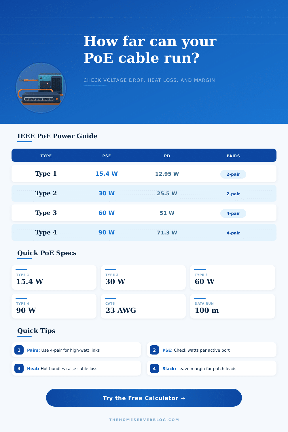
| IEEE mode | Class | PSE power | PD power | Power pairs | Planning note |
|---|---|---|---|---|---|
| 802.3af Type 1 | 0-3 | 4.0-15.4 W | 3.84-12.95 W | 2-pair | Phones, basic cameras, low-power APs. |
| 802.3at Type 2 | 4 | 30 W | 25.5 W | 2-pair | Most Wi-Fi 5/6 APs and larger cameras. |
| 802.3bt Type 3 | 5-6 | 45-60 W | 40-51 W | 4-pair | Thin clients, small switches, high-power APs. |
| 802.3bt Type 4 | 7-8 | 75-90 W | 62-71.3 W | 4-pair | PTZ heaters, displays, and specialty devices. |
| Cable selection | Conductor | Loop Ω / 100 m | PoE suitability | Use in calculator |
|---|---|---|---|---|
| Cat5e solid copper | 24 AWG | 18.8 | Good for Type 1/2 at normal runs. | Common retrofit baseline. |
| Cat6 solid copper | 23 AWG | 14.8 | Better voltage margin and less heat. | Good default for home lab PoE. |
| Cat6A shielded | 22-23 AWG | 11.2-14.2 | Best for high-power bundles. | Use for Type 3/4 planning. |
| Slim patch cable | 26-28 AWG | 29-45 | Short patch use only for higher power. | Keep short or derate strongly. |
| CCA cable | 24 AWG CCA | 30+ | Not recommended for PoE delivery. | Use only to show risk. |
| Condition | Multiplier | Why it matters | Typical check |
|---|---|---|---|
| Open air tray | 1.00× | Heat escapes easily. | Loose cables, low fill. |
| Small bundle | 1.05× | Moderate warming raises resistance. | 7-24 cables in a path. |
| Dense bundle | 1.10× | More cable heating under PoE load. | 25-48 powered cables. |
| Hot conduit | 1.15× | Ambient heat reduces voltage margin. | Attic, wall, or conduit runs. |
| High-density PoE | 1.22× | Conservative allowance for large bundles. | Many Type 3/4 links together. |
| Planning limit | Value | Formula signal | Practical use |
|---|---|---|---|
| Ethernet channel | 100 m / 328 ft | Data limit, not power formula. | Includes patch cords and permanent link. |
| Copper resistance | R rises with heat | R = R20 x [1 + 0.00393 x (T - 20)]. | Hot bundles lose more voltage. |
| 4-pair PoE | Half effective R | Two powered pairsets in parallel. | Lower drop and lower heat per pair. |
| PSE budget | Total PSE watts | Total = per-link PSE watts x links. | Compare after safety margin. |
When you install a network cable for a ceiling access point or an outdoor camera, you have to consider whether the power will reach the device once the network cable becomes warm and the length of the cable increase. Power over Ethernet technology allow power to be provided to the network device through the network cable, eliminating the need to run power lines to the device. The copper contained in the network cable becomes part of an electrical circuit.
The resistance of the copper increases as the length of the network cable increases, the temperature of the cable increases, and the number of network cable sharing the same pathway increases. The calculator application allow users to perform the mathematical calculations necessary to determine the voltage drop in the network cable due to these factors. Thus, using the calculator prevents the engineer from having to manually calculate the voltage drops in the network cable.
How to check voltage drop in Ethernet cables
The temperature of the network cable affect the resistance of the copper in the network cable. When the temperature of the network cable increases, the voltage drops along a bundle of network cables located, for instance, in an attic may fail to provide the voltage necessary for proper operation of the device connected to those cables. The resistance of the copper in the network cable increases by approximately four-tenths of a percent for every degree in Celsius in which the temperature of the cable increases above the room temperature.
Thus, a short length of network cable may appear to provide the voltage necessary to operate the network device. However, the voltage drop along the short length of the network cable may not provide the voltage to the network device if the temperature of the network cable increase. The calculator includes a bundle derating factor that is applied to the resistance of the network cable to account for the fact that network cables bundle together increase in temperature due to the current passing through each network cable.
For network cables that are contained in a loose tray the bundle derating factor is close to one. For network cables that are contained in a crowded conduit the bundle derating factor can reach one point two two. Using one point two two as the bundle derating factor for a set of network cables will reduce the safe distance of those network cables by twenty percent or more.
The number of pair that are used to carry power also impacts the resistance of the network cable. Using four pairs to carry power to a network device rather than two pair will reduce the resistance in the network circuit. High-power 802.3bt devices use four pair to carry power to the device to reduce the resistance in the circuit created by the network cable.
The calculator includes fields for entering the number of pairs used to carry power to the device. Thus, the network installer can use the calculator to determine the benefits of using four-pair power delivery rather than two-pair power delivery. The change in the number of pairs used for power will impact the calculated voltage at the powered device.
Thus, each change in the number of pairs will impact the heat loss that may occur along the link. Each patch panel that is connected to the network cable and each network jack will introduce a resistance into the network cable in the amount of a few hundredths of an ohm. Thus, the more patch panels and network devices along the network cable the resistance of the network cable increases.
Using aged patch panels and network jacks may increase the resistance along each patch panel and network jack to half an ohm. Half an ohm of resistance doesnt matter for network cables of twenty meters in length. However, half an ohm of resistance may reduce the voltage to a network device located at the end of a network cable of ninety meters in length to the edge of the voltage level that will allow the network device to continue to properly function.
The calculator displays the resistance of the network cable and the patch panels and network jacks that is connected to the network cable. The resistance of the copper in the network cable can be reduced by using solid twenty-three AWG copper cable rather than solid twenty-four AWG copper cable. For these reason many network installers use Category 6 (Cat6) cable for their network installations.
However, the patch cords at each end of the link to the network device can also impact the network device’s power delivery. For these reasons a short length of twenty-eight AWG slim patch cords may negate the benefit of using Cat6 cable for the link between the switch and the patch panel. The calculator considers the entire link between the switch and the network device as one single loop in the network circuit.
Thus, the network designer can use the calculator to determine if the patch cords will have any impact on the network link. The Power Sourcing Equipment (PSE) budget for power delivery to the device is another consideration. The switch that provides power to the network device must supply enough power to the device to meet the power that is consumed by the device.
In addition, the switch must supply enough power to overcome the heat loss that occurs in the network cable. Finally, the switch must supply enough power to the network device to provide a safety margin for the network device. If many network devices is connected to a switch the power requirements for the switch will quickly multiply.
The safety margin in the calculator can be adjusted to provide headroom for the switch for power to network devices that may be added in the future or for network devices whose power requirements are not controlled by the network installer. A ten percent safety margin is typically used in new installations. However, a twenty percent safety margin is applied when planning for future network devices or when the temperature of the network pathway cannot be controlled.
The specifications for network devices as defined by the IEEE only provide maximum limits on power delivery. For instance, a Type 2 switch can deliver a maximum of thirty watts of power to a network device. However, the network device can only recieve a minimum of twenty-five point five watt of power after the power is lost in the network cable.
Thus, if the network device requires eighteen watts of power to operate the switch can be determined using the calculator if the remaining budget for the switch will support the power requirement of the network device with the safety margin. If the power budget for the switch is not sufficient, steps can be taken to increase the power delivery to the device such as decreasing the length of the network cable, increasing the thickness of the network cable, four-pair power delivery, or use of a higher voltage supply from the PSE. The real world often include factors that impact power delivery to the network device that are outside of the considerations of the IEEE specifications.
Factors such as high temperatures in the attic, shared pathways with lighting circuits and other network devices that contribute to the heating of the network cables, and the growing number of network devices that share the same network pathways will contribute to the resistance of the network cable. While the calculator does not measure these environmental factors the effects of these factors can be made visible to the network installer by adjusting the temperature and bundle fields. Thus, the ability to adjust these fields makes it possible to make a decision that avoids network devices that may need to reboot to regain access to the network.
The best method for installing network cables that carry power to network devices involves determining the length of the link between the switch and the network device. It is to be determined that the length of the link between the switch and the device should include the length of the patch cords between the network device and the patch panel at which the power is received by the device. The resistance of the network cable will be reduced if the cable that is selected for installation is selected based off the power class of the device.
Rather than choosing the cheapest network cable it is possible to select a cable that reduces the resistance of that network cable. It is additionally important for network installers to use a realistic factor for the temperature of the network cable and the number of network cable sharing the same pathway. Finally, it is important for the installer to allow the calculator to determine if the link will meet both the power limits of the network device and the data limits of the network cable.
If the margin for error in the network link is thin the network installer should adjust for the length of the network cable or the thickness of the network cable. Thus, a thin margin for error indicates that shorter or thicker network cables should be used.