RS-485 Cable Length Calculator
Estimate RS-485 bus reach from baud rate, cable gauge, capacitance, node loading, termination, biasing, voltage drop, and usable noise margin.
🖧Industrial and home automation presets
Pick a common RS-485 installation, then tune baud rate, trunk length, cable, nodes, termination, bias network, and load current for your bus.
⚙RS-485 bus inputs
RS-485 bus result
📊RS-485 cable spec grid
📘Reference tables
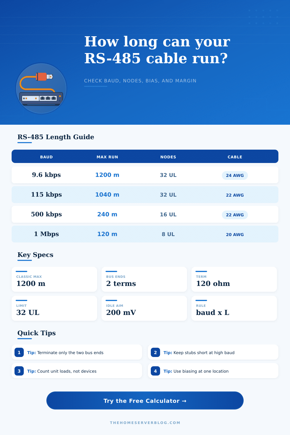
Baud rate versus conservative trunk length
| Baud rate | Common planning length | Best cable choice | Design note |
|---|---|---|---|
| 9,600 to 19,200 bps | Up to 1,200 m / 3,937 ft | 24 AWG shielded pair or larger | Good for Modbus meters, gates, tanks, and remote I/O. |
| 38,400 to 76,800 bps | About 1,000 to 1,200 m when the bus is clean | 22 AWG shielded twisted pair | Common for BACnet MS/TP and building controls. |
| 115,200 bps | About 900 to 1,040 m before extra derating | Low-capacitance 22 AWG pair | Keep stubs short and avoid star wiring. |
| 250,000 bps | About 480 m from the baud-length rule | DMX-rated 120 ohm cable | Use real daisy-chain topology and matched end termination. |
| 500,000 to 1,000,000 bps | About 120 to 240 m before margin checks | Low-capacitance cable, short stubs | Validate with scope or protocol error counters. |
Cable gauge, capacitance, and resistance guide
| Cable type | Typical capacitance | Loop resistance | Practical fit |
|---|---|---|---|
| 24 AWG shielded RS-485 pair | 43 pF/m | 168 ohms/km | Standard controls trunk and meter networks. |
| 22 AWG shielded RS-485 pair | 45 pF/m | 106 ohms/km | Longer building automation loops with lower drop. |
| 20 AWG low-capacitance pair | 42 pF/m | 67 ohms/km | Longer runs with powered sensors or heavy biasing. |
| 18 AWG outdoor pair | 40 pF/m | 42 ohms/km | Gates, tanks, solar equipment, and field panels. |
| Cat5e or Cat6 pair | 50 to 52 pF/m | 144 to 188 ohms/km | Acceptable for short indoor runs when impedance is suitable. |
Node count, termination, and biasing checks
| Item | Planning target | Calculator check | Why it matters |
|---|---|---|---|
| Receiver unit load | 32 UL or less per segment | Nodes multiplied by unit load | Too much receiver load reduces differential signal margin. |
| Termination | One 120 ohm resistor at each bus end | Equivalent load of 60 ohms with two ends | Prevents reflections but increases driver current. |
| Bias network | One bias point, often 390 to 1,000 ohms per leg | Idle differential across the termination load | Keeps an idle bus in a known fail-safe state. |
| Stub length | Shorter as baud rises | Compares stub time against bit time | Long stubs act like unterminated transmission-line branches. |
Common RS-485 project sizes
| Project | Typical baud | Typical nodes | Length focus |
|---|---|---|---|
| Home energy meter chain | 9,600 to 19,200 bps | 4 to 20 meters | Long trunk margin and clean bias at one gateway. |
| BACnet air-handler loop | 38,400 to 76,800 bps | 10 to 40 controllers | Fractional-load receivers and correct end termination. |
| DMX lighting universe | 250,000 bps | Up to 32 receivers | 120 ohm cable, short drops, and no star topology. |
| Solar inverter Modbus | 19,200 to 38,400 bps | 2 to 16 inverters | Outdoor shielded cable and voltage drop on any power pair. |
| PLC bench network | 115,200 to 1,000,000 bps | 2 to 8 devices | Short trunk, tight stubs, and measured noise margin. |
💡RS-485 planning tips
An RS-485 length calculator is a tool that will help you to determine whether or not your RS-485 network will functions correctly. A RS-485 network allows for multiple device to communicate over a single cable. A variety of different physical variable can affect the functionality of these networks.
The physical variables to consider include the length of the RS-485 cable, the speed at which the data are to be communicated, and the number of devices that will be connecting to that RS-485 cable. Each of these variables has the potential to impact the other variables, which means that altering one will alter the maximum length of the cable that the RS-485 network can use. An RS-485 length calculator will help you to input each of these variable into the calculator to determine a single number that will indicate whether or not the RS-485 network will function correct.
How to Use an RS-485 Length Calculator
One of the first variables that will affect the functionality of the RS-485 network is the baud rate. The baud rate will help to determine at what speed the data will travel along the cable. Data that travels at a fast baud rate will have less time for the signal along the RS-485 cable to rise or fall.
Thus, data that can be sent at a low baud rate may not be able to travel at a high baud rate. The second of the variables to consider is the type of cable that will be used. Each type of cable will have its own level of capacitance and resistance.
An RS-485 length calculator will allow you to input these properties of the cable to reflect their impact upon the length of the cable that the RS-485 network will use. The third variable to consider is the number of node that will become part of the RS-485 network. Each node will draw some of the current from the RS-485 data cable.
The more nodes that are added to the network, the more the load upon the RS-485 data cable increase. Each node has a unit load rating, and by multiplying the number of nodes by the load of each node, you can determine the total load upon the RS-485 data cable. Any total load that is too high will cause the driver to not be able to supply enough voltage to each node.
Thus, the RS-485 length calculator can help to determine if the number of nodes is too high for the RS-485 network. The fourth of the variables to consider are the termination and bias resistor that will be added to the RS-485 data cable. You will add termination resistors to the end of the RS-485 data cable to prevent signal reflections from the cable.
A 120-ohm resistor should be placed at each end of the data cable. Bias resistors will also be used in the RS-485 data cable, but for a different purpose than the termination resistors. Bias resistors will create a voltage along the data cable that allow for the data to be sent when the devices are not in use.
Without bias resistors, the electrical noise along the data cable may be mistaken for data by the devices along the RS-485 network. An RS-485 length calculator that considers each of these termination and bias resistors will ensure that the correct value of each type of resistor is placed into the RS-485 network. The fifth variable to consider is the voltage drop and noise margin.
If you are to send the power for the devices along the RS-485 data cable along that same RS-485 cable, then the voltage will drop along that cable due to its resistance. Thus, the voltage along the data cable will need to be high enough to both exceed the threshold voltage for the devices to recognize the signal, as well as to remain readable despite any electrical noise along the cable. Any electrical noise along the cable will decrease the readability of the data sent along the RS-485 data cable.
An RS-485 length calculator will calculate how much noise margin will remain along the cable by subtracting the voltage of the electrical noise along the cable from the voltage of the signal. If the noise margin is a positive number, the signal will be readable along the RS-485 data cable. However, if the noise margin is a very small positive number, the RS-485 network may fails.
Finally, an RS-485 length calculator will provide you with an estimate as to the length of the RS-485 data cable based off the variables that you enter into the calculator. However, there are other variable, such as temperature changes and electrical noise that may exist outside of the parameters of the calculator that will impact the performance of the RS-485 data cable. For instance, changes in the temperature of the cable will impact the resistance of the cable.
Additionally, any electrical noise outside of that which is calculated by the length calculator will impact the readability of the signal. Thus, you should use the RS-485 length calculator to determine the length of the data cable that should be used. However, actual measurement of the voltage along the data cable to the most distant node and the counting of any bit errors along the RS-485 data cable will ensure that your network will function as intended.
Overall, then, the RS-485 length calculator is a helpful tool in that it allows you to convert these various and complex variables to a map of the capability of your RS-485 network. You’ll find it is actualy a moddern tool for any technician. It is better than guessing, and it should of been used for every installation.