RF Propagation Delay Calculator
Estimate RF one-way delay and round-trip time from path distance, air or vacuum velocity, frequency band, feedline delay, antenna group delay, repeater hops, and tropospheric path stretch.
| RF Medium | Velocity Factor | Delay per km | Practical Use |
|---|---|---|---|
| Vacuum | 1.0000 | 3.336 us | Satellite and high-altitude geometry planning |
| Dry air | 0.9997 | 3.337 us | Most line-of-sight terrestrial radio links |
| Humid lower air | 0.9996 | 3.337 us | Coastal, wet, or dense lower atmosphere paths |
| Tropospheric duct | 0.9993 | 3.338 us | Longer bent paths where geometry is uncertain |
| Coax feedline | 0.66 to 0.88 | 3.79 to 5.05 ns/m | Tower, mast, shack, and rooftop antenna cabling |
| Frequency Band | Typical Carrier | Wavelength | Delay Note |
|---|---|---|---|
| VHF 2 m | 146 MHz | 2.05 m | Propagation delay is distance-led; repeaters can dominate |
| UHF or GMRS | 433 to 462 MHz | 65 to 69 cm | Useful for hilltop relay and handheld timing estimates |
| ISM or LoRa | 868 to 915 MHz | 33 to 35 cm | Long symbol times often exceed pure path delay |
| Wi-Fi | 2.4 or 5 GHz | 5 to 12 cm | MAC contention usually dwarfs propagation indoors |
| Microwave and Ku | 11 to 12 GHz | 2.5 to 2.7 cm | Slant range and equipment timing matter for links |
| Feedline Type | Velocity Factor | Delay per 100 ft | Where It Appears |
|---|---|---|---|
| RG-58 foam or solid PE | 0.66 | 154 ns | Short station jumpers and legacy mobile radio runs |
| RG-213 | 0.66 | 154 ns | HF, VHF, and general-purpose shack feedline |
| LMR-240 | 0.84 | 121 ns | Wi-Fi, LoRa, scanner, and modest mast runs |
| LMR-400 | 0.85 | 119 ns | Low-loss VHF, UHF, and microwave rooftop runs |
| 1/2 inch hardline | 0.88 | 115 ns | Tower runs, repeaters, and base-station feeds |
| Preset Link | Distance Basis | Added Delay Source | Timing Takeaway |
|---|---|---|---|
| 5 GHz Wi-Fi Room | 30 m direct path | Small antenna and coax delay | Propagation is tiny compared with Wi-Fi contention |
| VHF Ham Repeater | 35 mi terrain path | One analog repeater hop | Path delay and relay delay both matter |
| 11 GHz Microwave | 18 mi line of sight | Hardline, filters, path factor | Sub-100 us timing is distance-sensitive |
| LEO Satellite Pass | 1200 km slant range | Vacuum path plus station feed | RTT changes quickly with satellite geometry |
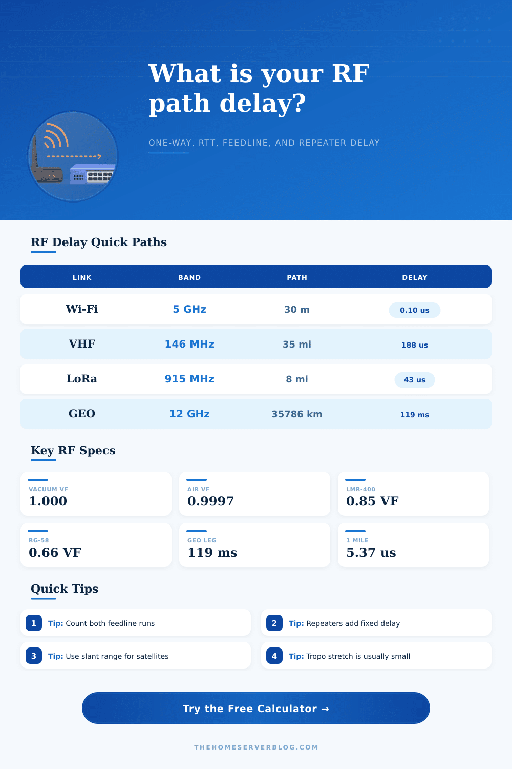
| GEO Uplink Leg | 35786 km slant range | Vacuum path and station RF chain | Single leg is already about 119 ms |
Maybe I can put out some radio wave and expect it to reach around the corner without any delay. A light beam travels so quickly it’s almost instant for us, but if you’re trying to build something time sensitive, that intuition is deadly. Each hop through a repeater, each foot of cable add latency. The slight change in air density along the way also contribute too. Getting familiar with those latencies will distinguish your functional radio link from one that fail when loaded.
By entering your hardware specs and the distance your path covers, the calculator do all the math. It also prevents you from having to look up velocity factor for various types of coax.
Understanding Signal Delay
A common error made by engineers is to assume the air path is the only variable. In most local links such as Wi-Fi or VHF ham radio, the physical distance typically contribute only a fraction of a microsecond. Instead, it’s the feedline coming in through door of the equipment shed and up the tower that can contributes the majority of the delay. Depending on what kind of dielectric material they contain, coaxial cables slow down the signals significently versus free space. Inside that plastic jacket, the signal travels at two-thirds the speed of light, or a velocity factor of 0.66. That’s why longer runs result in more delay, and it add up if you’re trying to keep multiple access point in sync or maintain a stable mesh network.
Velocity factor is a number, yes, but it mean something in terms of time. Even with 50 feet of coaxial cable connecting your antenna to your radio, it still takes measurable nanoseconds for the signal to move through the dielectric and out in the air. And just like signal loss, timing is important, so the tool want to know total feedline length and specific cable types you’re using. That’s when you throw repeaters into equation and instead of nanoseconds you get microseconds… maybe even milliseconds. Real analog repeaters aren’t too bad at all, but digital ones which do store-and-forward has some level of processing lag, which can be harmful to a real-time voice conversation or TDD protocol.
The medium is part of the equation too. Air isn’t quite empty, it have pressure (pressure gradients), humidity, and mass that slow down electromagnetic waves just a bit. That’s insignificant on a short terrestrial link. But when you’re talking tens of thousands of kilometers like satellite communications are, those small fractions makes all the difference. Because a GEO satellite is roughly thirty-six thousand kilometers away, there’s around 120 milliseconds of one-way delay. This explains why long distance satellite phone conversation sound like an echo. To account for this, the calculator offer three presets for the medium: vacuum, dry air, and humid atmosphere. It even accounts for the tropospheric path factor during rare ducting events. In these cases, the signal bends with layers of the atmosphere, making its path longer than a straight line would suggest.
That said, light travels at the same rate in the air regardless of frequency. It will determine antenna design and wavelength. This in turn affects the matching network and filter group delays. Microwave links at higher frequencies are more critical in their tolerance levels. If the cable length calculation is off by even a little at 11GHz, it may be enough to disrupt phase relationships and cause signals to cancel or create standing waves.
While the table on the page is helpful for different band behavior, the physics is all the same. Medium resistance and path length vary but not the speed. Propagation delay sucks. It’s not going away. Whether you’re deploying a rural sensor telemetry network using LoRa or setting up a point-to-point microwave bridge between two office building, knowing your total end-to-end (round-trip) time is important. This helps ensure that you use appropriate buffer sizes and modulation schemes so that your protocols don’t get confused. It’s simple math, but messier when it comes to implementing in hardware.
Measure your cables. Carefully. Include each hop through any repeaters. And remember: the universe has a few toll booths on its speed limit. You should of obeyed them.