Coax Cable Impedance Calculator
Calculate characteristic impedance, solve shield diameter for a target impedance, and estimate RF mismatch, capacitance, inductance, velocity factor, wavelength, and delay from coax geometry.
Coax impedance results
| Dielectric | Approx er | Velocity factor | D/d for 50 ohm | D/d for 75 ohm |
|---|---|---|---|---|
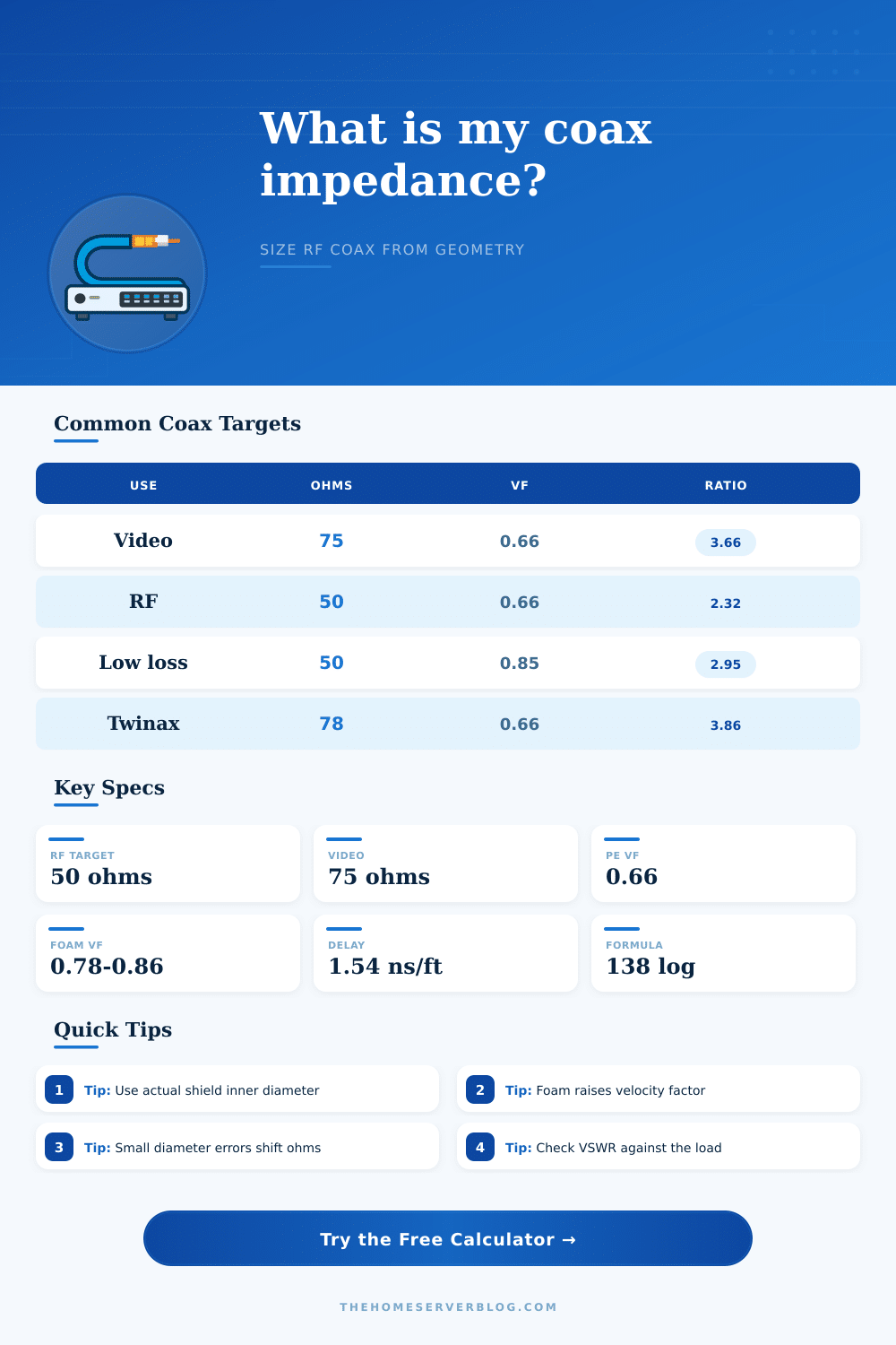
| Solid polyethylene | 2.30 | 0.66 | 2.32 | 3.66 |
| Foam polyethylene | 1.64 | 0.78 | 2.91 | 4.97 |
| Low-loss foam | 1.38 | 0.85 | 3.11 | 5.45 |
| Air-spaced support | 1.23 | 0.90 | 3.26 | 5.85 |
| PTFE | 2.05 | 0.70 | 2.57 | 4.18 |
| Cable family | Nominal impedance | Typical VF | Common use | Practical note |
|---|---|---|---|---|
| RG-58 | 50 ohm | 0.66 | HF/VHF jumpers | Short flexible RF leads |
| RG-8X | 50 ohm | 0.78 | Portable radio | Moderate loss and size |
| LMR-400 style | 50 ohm | 0.85 | Wi-Fi and VHF/UHF | Foam dielectric low loss |
| RG-59 | 75 ohm | 0.66 | Baseband video | Higher capacitance than RG-6 |
| RG-6 | 75 ohm | 0.82 | CATV and satellite | Foam dielectric, low loss |
| RG-62 | 93 ohm | 0.84 | Low capacitance | Legacy data and pulse lines |
| System target | Why it is used | Geometry tendency | Mismatch warning | Home lab example |
|---|---|---|---|---|
| 50 ohm | Power handling balance | Smaller D/d | 75 ohm cable gives 1.50:1 | SDR transmit, ham radio |
| 75 ohm | Low attenuation near optimum | Larger D/d | 50 ohm cable gives 1.50:1 | TV, CCTV, receive antennas |
| 78 ohm | Pulse and timing work | Slightly larger than 75 | Check return loss on fast edges | Timing distribution |
| 93 ohm | Low capacitance line | Large D/d | Often not for RF power | High impedance sensors |
| Formula item | Expression | Input units | Output | Use in calculator |
|---|---|---|---|---|
| Impedance | 138 log10(D/d) / sqrt(er) | Same diameter units | Ohms | Main geometry result |
| Required ratio | 10^(Z sqrt(er) / 138) | Ohms and er | D/d | Target shield solve |
| Capacitance | 2 pi eps er / ln(D/d) | Meters | pF per length | Loading estimate |
| Inductance | mu ln(D/d) / 2 pi | Meters | uH per length | Transmission line constant |
| VSWR | (1 + gamma) / (1 - gamma) | Impedance ratio | Ratio | Mismatch estimate |
Coaxial cable is an component that is used to transmit radio frequency signals. For teh coaxial cable to function correct, it must have a specific characteristic impedance. The characteristic impedance of a coaxial cable is not the same than the resistance of the cable, which a multimeter can measure.
Instead, the characteristic impedance of a coaxial cable is the ratio of the electric fields to the magnetic fields created by the signal that propagate along the coaxial cable. This ratio is calculated from the physical geometry of the coaxial cable. The physical geometry of a coaxial cable include the diameter of the inner conductor, the inner diameter of the shield, and the dielectric material that exist between the inner conductor and the shield.
How coaxial cable size and insulation change its impedance
If any of these components of the physical geometry of a coaxial cable are change, the characteristic impedance will change. The dielectric material exist between the inner conductor and the shield of the coaxial cable. The dielectric material determine the velocity factor of the signal in the coaxial cable.
The velocity factor is a measurement of the speed at which the signal propagate through the coaxial cable. Many types of dielectric material can be used in coaxial cable. For example, solid polyethylene and foam dielectric is two common types of dielectric materials used in coaxial cables.
Because the foam dielectric contains air bubbles, the signal travels at a more fast velocity through the coaxial cable then if solid polyethylene was used as the dielectric material. Thus, if the coaxial cable is to be used for time critical applications, such as in high power amplifiers, the velocity factor of the dielectric material will be a critical factor in the performance of those component. Coaxial cables can have different standard impedance.
For example, most radio frequency systems utilize a standard impedance of 50 ohm. In contrast, many video systems use a standard impedance of 75 ohms. The main purpose of using 50 ohms is to allow for the even distribution of power within the coaxial cable while minimize the loss of that signal.
The main purpose of using 75 ohms is to minimize the attenuation of the signal as it propagate through the coaxial cable to television frequencies. If a user connects a coaxial cable with a characteristic impedance of 75 ohms to a radio frequency system with an impedance of 50 ohms, the resulting voltage standing wave ratio (VSWR) will be high. A high VSWR indicate that most of the signal is not traveling to the antenna, some of the signal is reflecting off of the antenna.
If the signal reflect off of the antenna within a high power amplifier, that reflected signal will generate heat in the amplifier and may lead to damage of the amplifier components. To calculate the impedance of a coaxial cable, the coaxial cable must be measured appropriate. The diameter of the coaxial cable must be measured from the conductive surface of the coaxial cable.
Thus, you should not use the outside diameter of the coaxial cable jacket to determine the diameter of the coaxial cable. More specifically, the diameter of the inner conductor and the inner diameter of the shield must be measured. For coaxial cables whose shield are braided metal, for instance, the inner diameter of the shield is the diameter of the inner surface of the braid.
If the diameter of the coaxial cable jacket is used in place of the inner diameter of the coaxial cable shield in the calculations for the impedance of the coaxial cable, the calculated impedance will be incorrect. The ratio of the diameter of the shield of the coaxial cable to the diameter of the inner conductor determine the impedance of coaxial cable. Thus, a large coaxial cable can have 50 ohms of impedance if the ratio of the diameter of the shield to the inner conductor are the same as a small coaxial cable with 50 ohms of impedance.
The physical properties of the coaxial cable can change in a way that alter the impedance of the coaxial cable. Changes to the physical properties of the coaxial cable that can alter the impedance of the coaxial cable include crushing the coaxial cable, bending the coaxial cable around corner, and crimping the coaxial cable poor. Each of these changes will change the geometry of the coaxial cable, which will change its impedance.
When designing coaxial cables, engineers must balance the loss of signal with the physical size of the coaxial cable. Coaxial cables with larger diameters and with a foam dielectric will have less signal loss then coaxial cables with smaller diameters and solid dielectric materials. The larger diameter, however, may not be compatible with the size of the chassis that contain the coaxial cable.
Through calculations, engineers can determine the diameter of the shield that is necessary for the coaxial cable to have the targeted impedance. By using these calculations, engineers can remove guesswork from the fabrication of coaxial cables. The targeted impedance of a coaxial cable will determine the geometry of the coaxial cable; the geometry of the coaxial cable will ensure that the signal travel from the source to the antenna without any reflection.