Cable Tray Bend Calculator
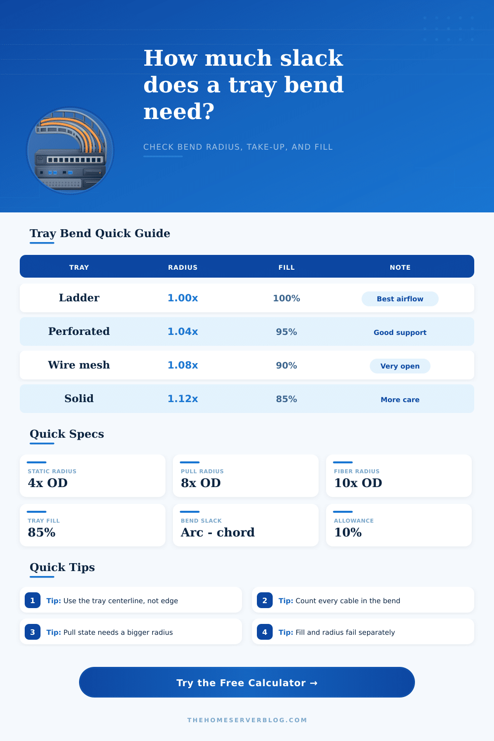
Check tray corner radius, bend take-up, and fill crowding before you commit a ladder, mesh, or solid-bottom bend.
Full Breakdown
| Tray Style | Bend Factor | Fill Factor | Use Case |
|---|---|---|---|
| Ladder tray | 1.00x | 100% | Open backbone |
| Perforated tray | 1.04x | 95% | Short bends |
| Wire mesh tray | 1.08x | 90% | Light bundles |
| Solid bottom tray | 1.12x | 85% | Tight support |
| Bend Family | Default Angle | Radius Factor | Note |
|---|---|---|---|
| 90° inside elbow | 90° | 1.00x | Standard corner |
| 90° outside elbow | 90° | 0.96x | Gentler sweep |
| 45° sweep | 45° | 0.92x | Lower take-up |
| 180° turnaround | 180° | 1.18x | Large reversal |
| Cable Type | Static | Dynamic | Example OD |
|---|---|---|---|
| Cat6A UTP | 4x OD | 8x OD | 0.25 in |
| OS2 fiber | 10x OD | 20x OD | 0.12 in |
| OM4 fiber | 10x OD | 20x OD | 0.11 in |
| Armored fiber | 15x OD | 25x OD | 0.24 in |
| Reference | Focus | Planning Rule | Reminder |
|---|---|---|---|
| NEC 392 | Tray systems | Check fill and support | Code wins over guesses |
| TIA-568 | Path design | Keep service loops | Protect active links |
| NEMA VE 1 | Hardware | Use listed fittings | Follow tray geometry |
| IEC 61537 | Tray ratings | Match load and span | Use the stricter rule |
This calculator keeps take-up, centerline radius, and bend crowding separate so you can see whether the tray corner is too tight, too crowded, or both.
Cable tray bend present different challenges then straight section of the same tray. Beyond the fact that the cables is compressed within a cable tray bend, the bend also change the space available to the tray’s cables. The cables that are on the inside of the bend is squeezed together, while the cables on the outside of the bend are stretch.
This squeezing of the cables can force the fill of the cable tray to go beyond the limits that is considered safely for that type of tray. It is easy for many to focus on an outer edge of a cable tray bend. However, to correctly calculate the amount of space that the tray’s cables will require, the radius of the bend need to be measured at the centerline of the tray.
How to Plan Cable Tray Bends
The type of cable tray that the installer uses will also change the way that the cables is managed within the bend. If the tray is of the ladder tray type, there is more space for the cables due to the open nature of the tray. A solid bottom tray will restrict the space for the cables and may require that the installer takes more care when the cables are being installed into the cable tray.
Each type of tray allow the cables to sit in a different way, and each type of tray can release heat from the cables differently. The wire mesh tray, for instance, may require more space due to the way the cables are crowded within the weave of the mesh. The way that the cables are installed into the cable tray can play a role in the cable tray bend.
During installation, when the installer pulls the cables into the tray, the dynamic radius of the cable can be larger then the radius of the cable tray bend. This is especially true of fiber optic cables. The requirements for different type of cables, such as PoE bundles or armored fiber cables, will change the mathematics of the cable tray bend.
Cable tray bend calculators will help determine if the cable tray can provide enough breathing room for the cables, or if it will be necessary to redo the installation of the cables into the tray. Many people makes mistakes with cable tray bends by ignoring side clearance and entry straights. Side clearance prevent the cables from being pinched against the side of the tray, and entry straights prevent the cables from piling up in a disorganized manner into the tray.
By ignoring these essential addition to the tray, the arc of the bend will create less space for the trays cables. Furthermore, a 90-degree inside elbow will create more stress upon the cables than a 45-degree sweep in the tray. For these two reason alone, it will be necessary to plan for more space when using 90-degree inside elbows.
Ambient heat can increase the temperature of the cables that are within the cable tray, especially if the tray is installed in a location such as a server riser. The cables may also experience vibration in there installation that can loosen the ties that hold each cable to the tray. If the installer calculates the cable tray bend correctly, there will be extra slack in the installation to accommodate for these environmental factor.
Furthermore, it is also important to plan for a conservative radius for fiber optic hybrid cables. In comparison, a generous radius can be planned for control wire. Making specific plans for these types of cables will ensure that they have enough space in which to breathe throughout the life of the installation.