EIGRP Metric Calculator
Compare classic and wide EIGRP metrics using bottleneck bandwidth, cumulative delay, load, reliability, MTU notes, and optional K-value tuning.
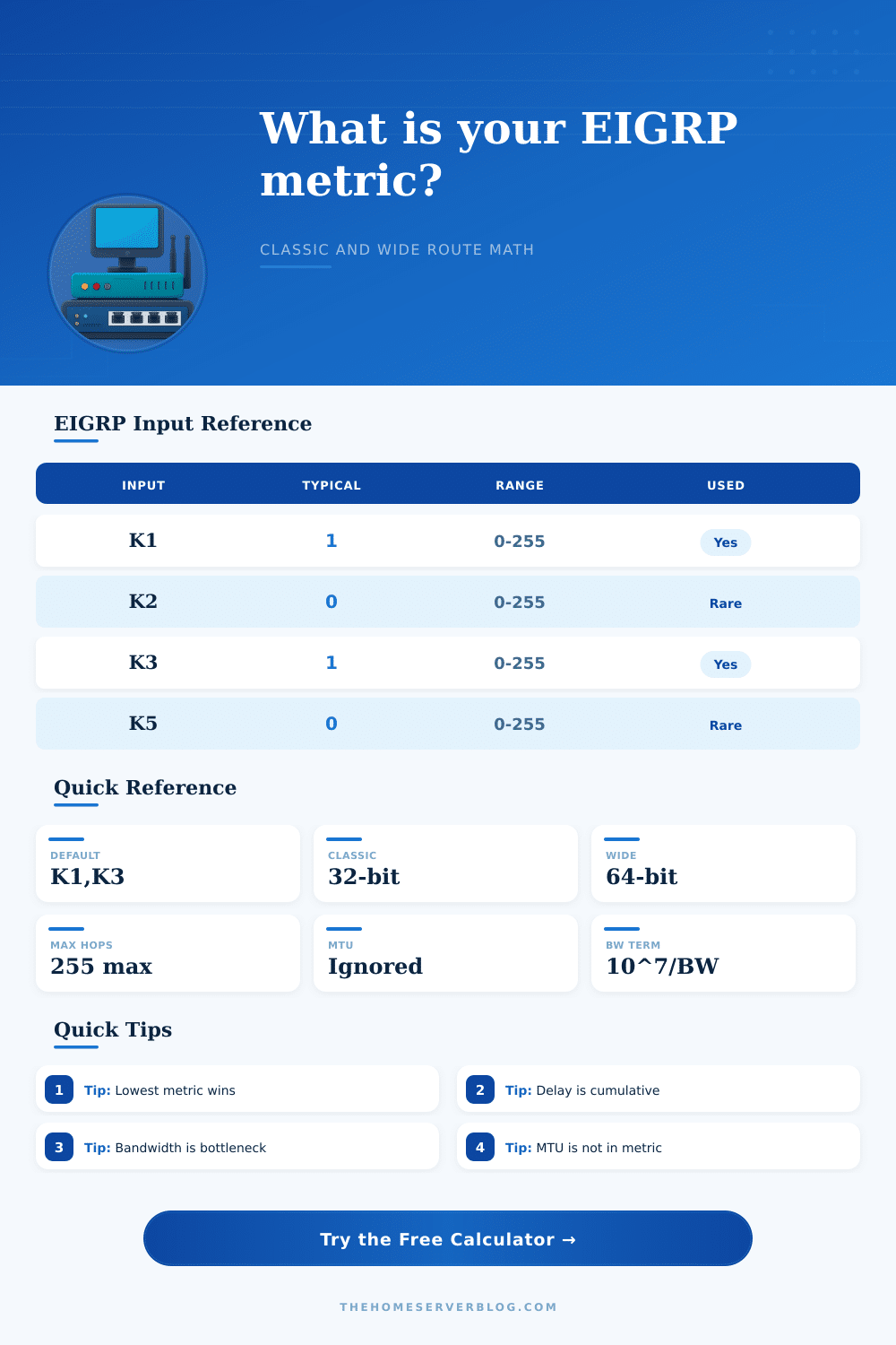
Default EIGRP uses K1 and K3 only. MTU is carried in routing updates but is not part of the composite metric calculation.
Calculated Route Metric
| Component | Default Behavior | Formula Role | Operational Note |
|---|---|---|---|
| Bandwidth | K1 enabled | 10,000,000 / minimum Kbps | Uses the slowest interface bandwidth in the route path. |
| Delay | K3 enabled | Sum of delays in tens of microseconds | Every outbound interface delay contributes to the path metric. |
| Load | K2 disabled | Uses 256 minus load as denominator | Rarely used because it can make route choice fluctuate. |
| Reliability | K4 and K5 disabled | Optional multiplier when K5 is nonzero | Keep K-values consistent across EIGRP neighbors. |
| MTU | Advertised only | Not included in metric math | Useful to inspect, but it does not decide the EIGRP metric. |
| Interface Type | Typical Bandwidth | Typical Delay | Metric Impact |
|---|---|---|---|
| 10G Ethernet core | 10,000 Mbps | 10 usec | Very low bandwidth and delay terms. |
| Gigabit Ethernet LAN | 1,000 Mbps | 10 usec | Common low metric for internal paths. |
| Fast Ethernet edge | 100 Mbps | 100 usec | Higher bottleneck term than gigabit. |
| Metro Ethernet handoff | 100 to 1,000 Mbps | 1,000 usec | Provider delay can dominate route choice. |
| T1 serial link | 1.544 Mbps | 20,000 usec | Very high metric from bandwidth and delay. |
| Satellite transport | 10 to 100 Mbps | 500,000 usec | Delay term can overwhelm faster bandwidth. |
| Scenario | Recommended K Values | Why It Works | Watch Point |
|---|---|---|---|
| Normal enterprise routing | K1=1, K3=1, others 0 | Stable bandwidth plus delay metric. | Keep interface bandwidth documented. |
| Lab comparison of two links | K1=1, K3=1, others 0 | Matches production defaults for testing. | Use identical K-values on all neighbors. |
| Load-sensitive experiment | K1=1, K2=1, K3=1 | Shows how load changes the composite value. | Can cause unstable path selection. |
| Reliability experiment | K1=1, K3=1, K5=1 | Applies reliability multiplier. | Never mix with default neighbors. |
| Project Size | Example Path | Expected Driver | Planning Result |
|---|---|---|---|
| Home lab rack | Two gigabit hops | Small delay differences | Metrics stay close unless bandwidth differs. |
| Branch office | LAN to WAN edge | WAN bottleneck | Lower committed rate usually loses. |
| Data center | 10G fabric path | Delay ticks | Wide metric helps preserve precision. |
| Backup VPN | Internet tunnel | Configured bandwidth | Set bandwidth intentionally for backup use. |
EIGRP use a composite metric to determine the best path for data packet. The composite metric consider several different factor when calculating a single value for each potential path for data packet. Each router utilize that composite metric to determine which path to use for data packet, and the routing table will always show the route with the lowest value of the composite metric.
Because EIGRP consider several different factors in the composite metric, it is possible for a network engineer or individual user to perceive a more higher perceived speed for data packet for the selected route, but the router is selecting that path according to a rules created by the composite metric. The composite metric is calculated using the bandwidth and the delay for each route. These two metric are the most important for calculating the composite metric for EIGRP.
How EIGRP Chooses the Best Path
The bandwidth will feature the slowest link within that route, regardless of the bandwidth of the other link in that route. The delay for each route is the sum of the delay of each interface that the data packet pass through. For this reason, a route with many network interface will have a higher delay than a route with few network interfaces.
Thus, even if the bandwidth of a route is high, the high delay can cause that route to have a higher composite metric value. For most network and engineers, the default K-values are used to calculate the composite metric. The default K-values use the bandwidth and delay metric for determining the best path for data packet.
Some engineer will change the K-values to use the reliability or load of the links in the route. However, changing the K-values to use the load for the route will cause instability in the network. If the load of one of the link in the route change, the value of the composite metric will change, which can cause the router to constant change routes for that data packet.
This rapid switching of path is referred to as flapping, which can result in routing loop. Thus, using the default K-values for the bandwidth and delay metrics for the route is the preferred solution for most network. Another reason that moddern network need the use of wide metrics is that wide metrics provide more precision than the classic metrics.
Classic metrics use 32-bit math to calculate metrics for route, but 32-bit math isnt precise enough for the high speed of the 10G, 40G, and 100G link that are common in many modern network. Because of the imprecision of 32-bit math, the router could calculate two link of the same high speed to have the same metrics. The use of 64-bit math in wide metrics allow for the router to discern the small difference in speed between link with very high speed.
Therefore, if a network contains both old and new hardware, it is important for network engineer to understand both classic and wide metrics in order to plan the route of the data traffic in the network. EIGRP utilizes two specific value to help prevent the formation of routing loop in networks that use the protocol. These two value are the reported distance and the feasible distance.
The reported distance is the metric of the neighboring router, while the feasible distance is the metric of the data packet from the router itself to the destination IP address. If the reported distance of a neighbor are lower than the feasible distance of the router, the neighbor is considered to be a feasible successor. A feasible successor is essentially a backup route for the data packet in the event of the failure of the primary route of those packet.
If a router have a feasible successor, the router will converge to the new route without having to calculate a new feasible distance. When planning a network for a company or institution, it is important to consider the physical property of the link that will exist between the device in the network. For instance, link like satellite internet plan have high bandwidth but high delay in the delivery of those packet.
Because of the high delay in a satellite link, a router will calculate a high composite metric for that link. High composite metric will cause a router to consider that link a last resort for the data packet traveling through the network. These value for different link can be found in reference table, allowing engineer to create an engineering plan to establish the network.
If engineer calculate the composite metric of each link correctly, the router will take the route that engineer plan for the data packet.