Microwave Link Budget Calculator
Estimate free-space path loss, received signal level, fade margin, rain allowance, EIRP, and first Fresnel zone clearance for point-to-point home lab and building-to-building links.
Link Budget Results
| Band | Typical use | Planning concern | Practical note |
|---|---|---|---|
| 900 MHz | Low-speed obstructed paths | Noise floor and spectrum crowding | Better diffraction, larger antennas |
| 5 GHz | Home lab and campus bridges | Interference and channel width | Good gain options for short links |
| 6 GHz | Fixed wireless backhaul | Coordination and antenna size | Strong range when licensed or clean |
| 11 GHz | Longer licensed microwave hops | Fresnel clearance and fade margin | Common backhaul planning band |
| 18 GHz | Medium licensed rooftop hops | Rain fade becomes important | Use larger margin in wet regions |
| 23 GHz | Short licensed high-capacity links | Rain attenuation and alignment | Best for clean short paths |
| 60 GHz | Very short high-throughput bridge | Oxygen absorption and rain fade | Excellent reuse over small distances |
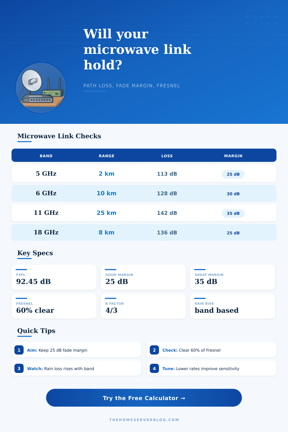
| Link role | Minimum margin | Preferred margin | When to add more |
|---|---|---|---|
| Temporary test bridge | 10 dB | 15 dB | Use for lab trials, not critical service |
| Home LAN extension | 15 dB | 25 dB | Add margin for trees, roofs, and weather |
| Primary building uplink | 20 dB | 30 dB | Add margin when remote access depends on it |
| Long licensed backhaul | 25 dB | 35 dB | Use path study data for final design |
| High rain band link | 30 dB | 40 dB | Needed above 18 GHz in wet regions |
| Path distance | 5 GHz 60% Fresnel | 11 GHz 60% Fresnel | Earth bulge at K 4/3 |
|---|---|---|---|
| 1 km | 2.3 m | 1.6 m | 0.01 m |
| 5 km | 5.2 m | 3.5 m | 0.37 m |
| 10 km | 7.3 m | 5.0 m | 1.47 m |
| 25 km | 11.6 m | 7.8 m | 9.19 m |
| 50 km | 16.4 m | 11.1 m | 36.76 m |
A wireless bridge is the connection between two antenna, but it can fail when the weather change. People will install two antennas with a line of sight to each other. However, having a line of sight does not ensure that the wireless bridge will work during a rainstorm.
There is a concept called the fade margin that describe the difference between the strength of the signal that will work during clear weather as opposed to bad weather. Engineers must plan for the fade margin to provide a buffer for case in which the signal weaken. A wireless bridge does not emit a signal in the same way that a laser emit light in a straight line.
Keeping a Wireless Bridge Working in Bad Weather
Instead, the signal travels through an elliptical volume known as the Fresnel zone. This zone exist in the space between the antenna in a line of sight to each other. If an object enter the Fresnel zone between the two antennas, that object will deflect the signal from the antennas.
Any deflection in the signal will cause interference with the signal, which will result in a reduction of the strength of the wireless bridge. The frequency use for a wireless bridge will determine the data speed and the reliability of the wireless bridge. Lower frequencies, such as 900 MHz, will allow the signal to travel through obstacle like leaves, but data speed will be low.
Higher frequencies, such as 5 GHz and 11 GHz, will provide higher data speeds but will allow the signal to travel through fewer obstacle. 60 GHz frequency will allow data to travel at the highest speed but rain will easily block it. Free Space Path Loss is a concept that define how a signal will weaken as the signal travels through the air.
When engineers use a calculator to calculate the Free Space Path Loss, they determine how much the signal will weaken as it travel through the air. However, there are other loss of the signal in the real world that are much more greater than the Free Space Path Loss. Cables, connectors, and the atmosphere will cause the wireless bridge to lose strength in the transmission of data.
Engineers must account for these loss by adding an engineering buffer to the Free Space Path Loss calculations. Rain fade is the loss in the strength of the signal of a wireless bridge due to rain droplet. The rain droplets will act as obstacle to the signal, reflecting and scattering the signal from the wireless bridge.
This will lead to a reduction of the strength of the wireless bridge. The more rain that fall on a wireless bridge in a specific area, the more rain fade the signal will experience than a wireless bridge in a dry area. By knowing how much rain allowance there is in a specific area, engineer can determine if a larger antenna or a more powerful transmitter is need.
The Earth is not flat; it is a sphere. For short distance, the curvature of the Earth is negligible. However, over long distance, the bulge of the Earth will enter the path of the signal.
The K factor is used to calculate how the atmosphere will bend the signal to account for the curvature of the Earth. If the engineers do not account for the curvature of the Earth when the signal is traveling from one antenna to another, the signal will reflect off the ground. Any signal that reflect off the ground will create multipath interference.
Multipath interference will lead to a reduction of the throughput of the wireless bridge. The goal for engineer is to ensure that the signal strength that is received is higher than the sensitivity of the receiver. If the signal level is too close to the receiver sensitivity, the wireless bridge will be unstable.
If the signal level is much higher than the sensitivity of the wireless bridge receiver, then there is a high fade margin between the signal strength and the level required to power the wireless bridge without instability. The fade margin need to be high enough to ensure the stability of the wireless bridge. However, the power of the wireless bridge must be set to a level that does not violate the rules of the local area regulation.
By calculating the Fresnel zone, the rain fade, and the hardware loss, engineers can ensure that the wireless bridge will function within many different weather condition.