VSWR Mismatch Loss Calculator
Convert VSWR, return loss, reflected power, reflection coefficient, or complex load impedance into mismatch loss, delivered RF power, return loss, and antenna-system risk for home lab radios, repeaters, analyzers, and RF bridges.
Formula Breakdown
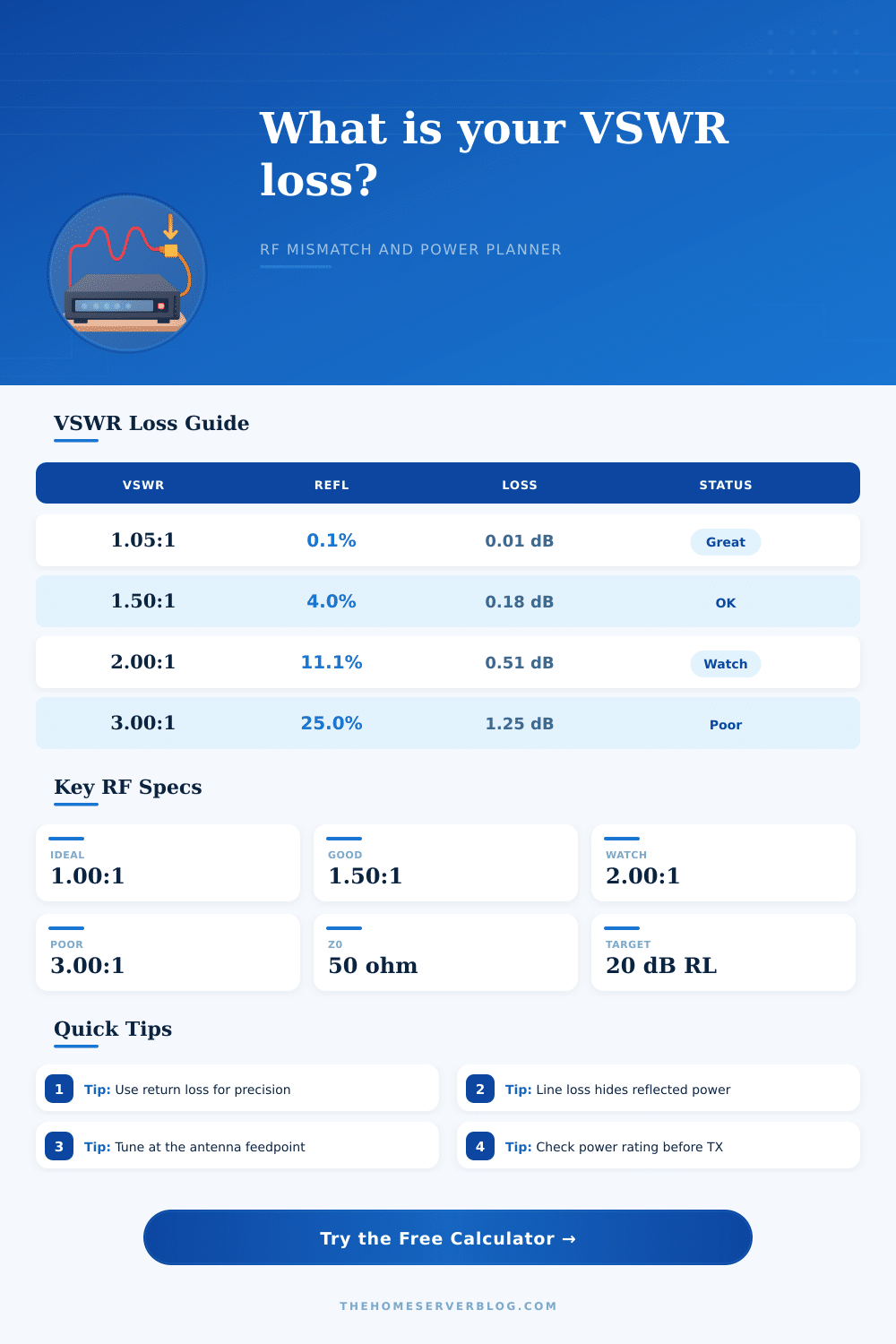
| VSWR | Reflection coefficient | Reflected power | Mismatch loss | Return loss |
|---|---|---|---|---|
| 1.05:1 | 0.0244 | 0.06% | 0.003 dB | 32.3 dB |
| 1.20:1 | 0.0909 | 0.83% | 0.036 dB | 20.8 dB |
| 1.50:1 | 0.2000 | 4.00% | 0.177 dB | 14.0 dB |
| 2.00:1 | 0.3333 | 11.11% | 0.512 dB | 9.5 dB |
| 3.00:1 | 0.5000 | 25.00% | 1.249 dB | 6.0 dB |
| Measurement input | Primary formula | Best use | Watch point |
|---|---|---|---|
| VSWR | Gamma = (S - 1) / (S + 1) | Antenna analyzers and transmitter meters | Low-resolution meters hide small loss changes |
| Return loss | Gamma = 10 ^ (-RL / 20) | VNA sweeps, lab fixtures, RF jumpers | Higher return loss means better match |
| Reflected power | Gamma = sqrt(Pref / Pfwd) | Directional wattmeters and couplers | Forward and reflected samples need calibration |
| Impedance | Gamma = abs((ZL - Z0) / (ZL + Z0)) | Complex load checks at a single frequency | Reactance can create a severe mismatch |
| Scenario | Typical target | Practical meaning | Calculator setting |
|---|---|---|---|
| HF tuner output | 1.5:1 or better | Usually acceptable for many radios after tuning | VSWR mode, 50 ohm Z0, tuner output power |
| Repeater duplexer path | 20 dB return loss or better | Stable match helps protect high-duty RF hardware | Return loss mode with rated transmitter power |
| Microwave jumper | 15 to 25 dB return loss | Small fixture errors matter at higher frequencies | Return loss mode plus measured insertion loss |
| CATV mismatch check | 75 ohm reference | Using 50 ohm assumptions gives wrong VSWR | Impedance mode with 75 ohm Z0 |
| System type | Z0 | Good planning range | Home lab note |
|---|---|---|---|
| Amateur HF/VHF/UHF | 50 ohm | 1.0:1 to 1.5:1 | Feedline loss can make shack VSWR look better than antenna VSWR |
| Wi-Fi and ISM RF | 50 ohm | 10 to 20 dB return loss | Adapters and pigtails can dominate the final mismatch |
| CATV and receive plant | 75 ohm | 15 dB return loss or better | Use the correct impedance reference before comparing readings |
| Balanced feed reference | 300 ohm | Design-specific | Transformers and baluns add their own match limits |
This calculator estimates RF mismatch behavior for planning and troubleshooting. Confirm high-power systems with calibrated instruments, rated loads, proper duty-cycle limits, and manufacturer protection guidance.
When the antenna and the feedline are not perfectly matched to the radio, some of the power that is sent to the antenna dont actualy reaches the antenna; instead, the power reflect back towards the transmitter. This reflected power is known as “mismatch loss” and it occurs on every frequency band, from HF through to the microwave frequency range. A clean match and a sloppy match may appear similar on paper, but they are vastly different in practice; there is additional factors to consider (like feedline attenuation, connector losses, and protection circuits that exist within the transmitter).
The ratio that is used to describe the antenna and feedline match is known as the VSWR (Voltage SWR Ratio). The VSWR describe the relationship between the highest voltage and the lowest voltage on the transmission line. An ideal ratio of antennas and feedlines will exhibit a VSWR value of 1:1; however, real systems will have a VSWR value that is more higher than 1:1.
VSWR and Antenna Power Loss
The specific value of VSWR that is measured will determine the quality of the match between the antenna and the feedline. For instance, an operator may be satisfied with a VSWR of 1.2:1. A VSWR of 1.5:1 mean that there is a modest amount of reflected power.
If the VSWR reaches 2:1, many radios will begin to folding back the power that is being sent to the antenna; if the VSWR reaches 3:1, the system is considered to be compromised. The calculator will perform the mathematics to determine how much of the forward power reach the load after accounting for reflected power. An alternative to VSWR that is used to describe the same concept is the measurement known as return loss.
Return loss is expressed in decibels (dB) rather than in a VSWR ratio. Higher return loss values are better then lower return loss values. For instance, a return loss of 20 dB will exhibit a VSWR of approximately 1.22:1.
A return loss of 20 dB is a common target for lab fixtures and critical jumpers because a return loss of 20 dB indicates that the reflected power is less than 1%. The calculator allows the user to switch between VSWR and return loss values to reflect the measurement that the measurement instrument provide. Impedance is the reason that VSWR and return loss measurements can change.
The resistance and reactance of the antenna load can differ from the characteristic impedance of the feedline. In these instances, a reflection coefficient exist within the transmission line. The calculator allows for complex impedance to be entered and will calculate the results of using a 75 ohm television antenna on a 50 ohm system, for instance, or will calculate the results of using a reactive whip antenna that is not in resonance with the transmitter.
Feedline loss can contribute to a misconception regarding the true VSWR of the antenna; many antenna operators is surprised at the VSWR at the shack versus the VSWR at the antenna. Coaxial cable will attenuate both the forward and reflected waves as they travel along the line. The calculator accounts for feedline loss; it permits the user to enter the one-way loss of the coaxial cable and the connectors separately from the VSWR loss.
The calculator will report the power that was lost from the transmitter to the antenna, in addition to the power reflected at the antenna. In addition to the parameters described above, it is important to also consider the power ratings of the radio, as well as the protection circuits installed in the radio. Many radios will permit VSWR ratios of 2:1 for short periods of time.
However, the radio may reduce its power output or turn off altogether if the VSWR remain high during continuous operation. The calculator permits the entry of the threshold for warning versus failure of the radio, as well as the power margin with which the antenna is to be design. Additionally, the calculator permits the comparison of the power that is delivered to the antenna to the power rating of the antenna itself.
This allows the operator to understand if the antenna is being asked to handle more power than it is able to handle. Tables are included in this article to show the relationship between VSWR, the reflection coefficient, the percentage of reflected power, the mismatch loss in decibels, and the return loss. These tables exist to allow the operator to quickly refer to these parameters without having to utilize the calculator to determine each parameter.
The same formulas that are utilized in the tables are the same that are utilized in the calculator. One of the most common mistake in radio operation is to treat VSWR as a parameter that is specific to the antenna. VSWR is a parameter that is established along the entire path from the radio to the antenna; the path includes the transmitter output connector, all adapters, jumpers, and the feedline.
Factors like temperature, moisture, and the movement of the antenna or feedline can change a marginal VSWR to a poor VSWR. By measuring VSWR at the feedpoint of the antenna, the effect of the feedline can be remove; VSWR measured at the feedpoint will provide a more accurate picture of the antenna itself. Assuming that a low VSWR ratio means that the antenna is efficient is another of the most common mistakes.
For instance, a dummy load will exhibit a VSWR of 1.05:1; however, it will dissipate every watt of power that is provided to it. By using the calculator to separate mismatch loss from other types of loss, the operator can learn that a good VSWR ratio does not necessarily mean that the antenna will be efficient radiating the radio signals. Finally, the best way to use this information is to treat VSWR as just one data point among many that should be used to make decisions regarding the antenna system.
The calculator will allow the user to convert the VSWR reading into delivered power, reflected power, and any other relevant parameter. Based on these values, the operator can decide if any adjustments must be made to the antenna to improve its performance. Making these corrections early on in the performance of the system will save the user more money and effort than if the system is allowed to fail and the transmitter is forced to work to protect itself from damage.