VSWR Reflected Power Calculator
Convert VSWR, return loss, reflected percentage, or measured reflected power into reflected watts, delivered watts, mismatch loss, voltage stress, and a practical RF link verdict.
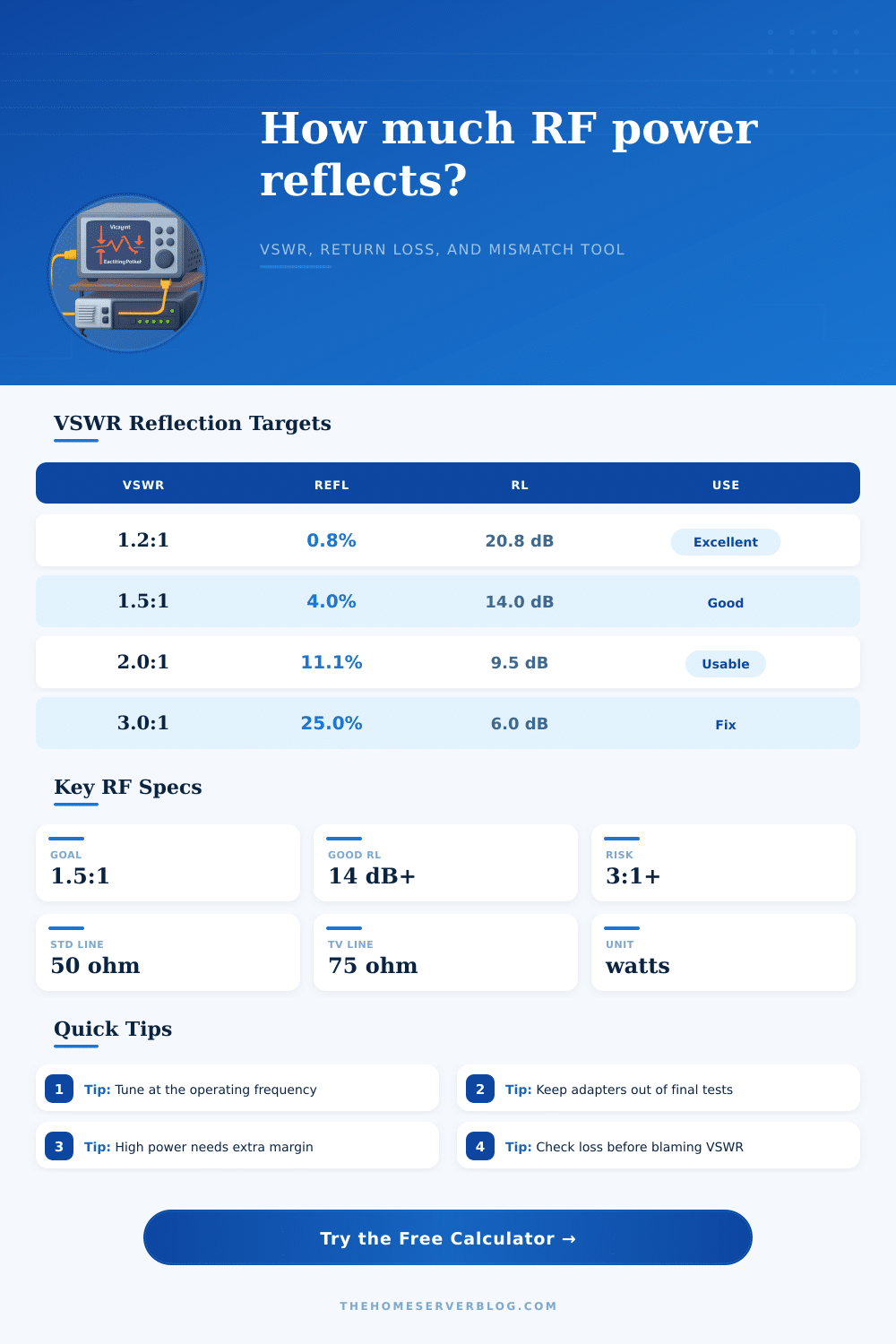
A 1.5:1 VSWR reflects about 4% of incident power before feed-line loss effects. High feed-line loss can hide a poor antenna match at the transmitter end.
VSWR, reflected power, and return loss targets
| VSWR | Reflected Power | Return Loss | Typical Action |
|---|---|---|---|
| 1.1:1 | 0.23% | 26.4 dB | Excellent lab match; normal cable and connector variation dominates. |
| 1.3:1 | 1.70% | 17.7 dB | Very good antenna or filter match for most home lab RF work. |
| 1.5:1 | 4.00% | 14.0 dB | Common practical target for mobile and base antennas. |
| 2.0:1 | 11.11% | 9.5 dB | Usable at reduced power if the transmitter is rated for it. |
| 3.0:1 | 25.00% | 6.0 dB | Tune, inspect, or lower power before long duty cycles. |
| 5.0:1 | 44.44% | 3.5 dB | Likely fault, wrong band, open feed, or serious impedance mismatch. |
Forward power examples at common VSWR values
| Forward Power | At 1.5:1 | At 2.0:1 | At 3.0:1 |
|---|---|---|---|
| 5 W handheld | 0.20 W reflected | 0.56 W reflected | 1.25 W reflected |
| 25 W mobile | 1.00 W reflected | 2.78 W reflected | 6.25 W reflected |
| 50 W base | 2.00 W reflected | 5.56 W reflected | 12.50 W reflected |
| 100 W HF rig | 4.00 W reflected | 11.11 W reflected | 25.00 W reflected |
| 500 W amplifier | 20.00 W reflected | 55.56 W reflected | 125.00 W reflected |
Coax and connector checks that affect the reading
| Component | Normal Concern | VSWR Symptom | Field Check |
|---|---|---|---|
| PL-259 adapter stack | Small impedance bumps | Higher UHF reading than VHF | Test with one known-good jumper. |
| Wet outdoor coax | Loss and corrosion | Low power with odd VSWR shift | Inspect braid, shield, and water entry. |
| Wrong antenna band | Reactance away from resonance | Sharp high VSWR across band | Sweep frequency to find resonance. |
| Too much feed-line loss | Bad antenna hidden by loss | Good shack VSWR, weak signal | Measure at antenna end if possible. |
| Under-rated dummy load | Heat changes resistance | VSWR rises during key-down | Use duty-rated load and short tests. |
Profile targets used by the calculator
| Profile | Target VSWR | Caution Point | Why It Matters |
|---|---|---|---|
| Home lab RF test bench | 1.3:1 | 1.8:1 | Bench measurements should not hide fixture errors. |
| Amateur radio station | 1.5:1 | 2.5:1 | Most modern rigs fold back above moderate mismatch. |
| GMRS or land mobile base | 1.5:1 | 2.0:1 | Continuous local service benefits from lower heating. |
| Wi-Fi or ISM link | 1.7:1 | 2.5:1 | Small mismatch can still matter in low-margin links. |
| Repeater or high duty cycle PA | 1.3:1 | 1.8:1 | Reflected power becomes heat over long transmit periods. |
| Satellite or microwave terminal | 1.4:1 | 2.0:1 | Return loss affects link budget and PA protection. |
An RF signal travel down the feed line toward an antenna. When the RF signal encounter a mismatch at the antenna, some of that RF signal energy reflect back toward the radio transmitter. The reflected RF signal energy can be measured in a variety of way (VSWR, return loss, reflected power).
Each of these value can be entered into the calculator. The calculator will perform the mathematics calculations necessary to determine the other reflected power values once you enter your known value. Each of these measurement has a meaning and purpose; understanding the various reflected power measurements will allow you to understand the usefulness of the reflected power calculations that the calculator can provide.
How to Use the Reflected Power Calculator
The first value to enter into the calculator is the forward power. The forward power is a measurement of how much energy leave the transmitter. The reflected power measurement will have no meaning unless you enter the forward power.
The forward power can be measured at many different point along the feed line, but most common at the radio end of the coaxial feed line. Because the power measurement is taken at the radio end of the coaxial feed line, the measurement include any loss that occurs within the coaxial feed line. Thus, the calculator will also ask for the line loss so that the calculator can determine the reflected power at the antenna (the load).
VSWR is just one of the many ways to describe the degree of mismatch between the antenna and the feed line. Return loss can also be entered, the percentage of reflected power, or the wattmeter reading of the reflected power. Each of these value will produce the same mathematical calculation of the reflection coefficient.
For example, when VSWR is 1.5 to 1, 4% of the forward power is reflect. This percentage can be converted to reflected watts by entering the forward power into the calculator. The reflected power will allow you to understand if the transmitter will fold back on itself or if the coaxial feed line will overheat.
Impedance is one of the factor that determines the standing wave voltage. For a 50 ohm impedance, the voltages will be low with low power values. For a 75 ohm television line, the standing voltage will be higher.
Thus, you must enter the impedance of the feed line into the calculator so that the estimated maximum voltage can be determine. The estimated maximum voltage will allow you to understand if the antenna or lightning arrestors are under more stress then expected. Duty cycle is entered into the calculator because reflected power become heat in the transmitter and feed line.
A voice station might have a 10% duty cycle while a repeater station may have a 100% duty cycle. The duty cycle entered into the calculator will allow for an understanding of how much reflected power become heat over time. The average heating load may be overlooked but it becomes a problem in situation where the amplifier reduce power or where connectors overheat during long nets.
The profile can be adjusted to show the targets for each of the reflected power measurement. For instance, a home lab station might have tighter targets than a temporary field station. Temporary field stations might have dirty connector or the antenna might be temporary erect.
These target will allow for the results to be understood and labeled as excellent, usable, or needing attention. The feed line loss before the antenna can be entered to determine the true reflected power at the antenna. A long run of feed line before the antenna might make the reflected power look good at the shack but the antenna might not be well matched to the feed line.
Thus, both the reflected power at the measurement point as well as the reflected power at the antenna can be determine with this measurement. Real installation will never be as ideal as calculated. Adapters will create some reflection.
The velocity factor of the coaxial cable can change with moisture content. The resistance of the antenna and feed line can change with temperature. These variable can be accounted for in the safety margin for reflected power.
For instance, a ten percent safety margin might be used for temporary installation but a twenty percent safety margin might be used for high power installation. There are reference table included with the calculator that list the reflected power at various forward power and VSWR values. These table also include the action to be taken for each reflected power level.
These table are useful in determining whether a measurement is within normal limit. Thus, the tables will allow you to know whether the measurement indicate a problem with the connector, the antenna being out of band, or an overheated load. The result will tell you how much power leave the antenna and how much power become heat.
With these value, you will be able to make a decision about whether the antenna is sufficient for your power level and duty cycle. Thus, the calculator eliminate the need for performing the mathematics yourself.