dB to Ratio Calculator
Convert decibels into power, voltage, and amplitude ratios with gain or loss direction, impedance-aware level changes, and cascaded audio, RF, or network stages.
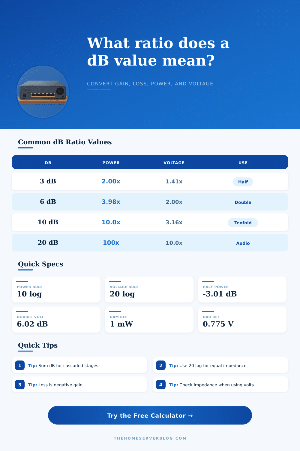
| dB Change | Power Ratio | Voltage / Amplitude Ratio | Practical Meaning |
|---|---|---|---|
| -60 dB | 0.000001x | 0.001x | Large RF path loss or noise rejection |
| -20 dB | 0.01x | 0.1x | Ten-to-one voltage pad |
| -10 dB | 0.1x | 0.316x | Common attenuator step |
| -6.02 dB | 0.25x | 0.5x | Half voltage or amplitude |
| -3.01 dB | 0.5x | 0.707x | Half power point |
| 0 dB | 1x | 1x | No gain or loss |
| 3.01 dB | 2x | 1.414x | Double power |
| 6.02 dB | 4x | 2x | Double voltage or amplitude |
| 10 dB | 10x | 3.162x | Ten times power |
| 20 dB | 100x | 10x | Ten times voltage |
| Unit | Reference | Conversion Idea | Common Use |
|---|---|---|---|
| dBm | 1 mW | dBm = 10 log(P / 1 mW) | RF, optical, Wi-Fi, link budgets |
| dBW | 1 W | dBW = dBm - 30 | Transmit power and amplifiers |
| dBV | 1 V RMS | dBV = 20 log(V / 1 V) | Consumer audio and test gear |
| dBu | 0.775 V RMS | dBu = 20 log(V / 0.775 V) | Professional audio levels |
| dBFS | Digital full scale | Relative to clipping point | ADC, DAC, DAW metering |
| SNR dB | Signal / noise | Ratio of signal to noise power | Receivers, audio interfaces, ADCs |
| Scenario | Typical dB | Ratio Focus | Planning Note |
|---|---|---|---|
| Microphone preamp | 20 to 60 dB | Voltage gain | Large voltage boost before conversion |
| Passive line pad | -10 to -30 dB | Voltage loss | Prevents clipping at the input |
| Speaker amplifier | 3 to 10 dB | Power gain | Small dB changes can need much more power |
| RF coax cable | -1 to -12 dB | Power loss | Loss grows with length and frequency |
| Antenna gain | 2 to 15 dBi | Power direction | Directional gain changes link budget |
| Wi-Fi path | -40 to -90 dB | Received power | Walls and distance dominate margin |
| Optical link | -3 to -25 dB | Power budget | Connector and fiber losses add directly |
| Digital headroom | -1 to -18 dBFS | Amplitude margin | Headroom protects peaks from clipping |
| Chain Type | Example Stages | Total Rule | What to Check |
|---|---|---|---|
| Audio input chain | Preamp, pad, insert, ADC | Add every dB stage | Clip margin and noise floor |
| RF receive path | Antenna, coax, filter, LNA | Gain minus cable and filter loss | Receiver sensitivity margin |
| Wi-Fi link budget | TX power, antenna, path, walls | Power terms add in dB | RSSI and SNR at the client |
| Optical network | Transceiver, fiber, splices | Losses add directly | Optical receive window |
| DSP level flow | Trim, EQ, compressor, output | Signed dB gain staging | Peak headroom at each block |
| Lab measurement | Generator, attenuator, probe | Apply stage signs in order | Instrument input range |
Decibels are use to measure signals. However, the readings on decibel are not direct measurements of the quantity of the signals. The decibel reading is a ratio that display the signal on a logarithmic scale.
The logarithmic scale allow small changes to the decibel number to indicate large change in the energy of the signal. The interpretation of the decibel number is essential since the number can represent the power, voltage, or amplitude of a signal. The use of a conversion tool are helpful in that it allows engineer to view the different kind of signals that pass through more than one stage of equipment.
Decibels and Signal Measurements
The quantity of the signal being measured determine the mathematical rules for that signal. For power ratios, engineers use the ten times rule of logarithms because the energy of a signal is the square of the voltage and current. For voltage or amplitude ratios, the twenty times rule is applied because voltage and amplitude is the linear measurements of power.
The wrong rule for calculating the signal will lead to nonsensical results. For instance, a six decibel increase in voltage means that the amplitude has doubled, but a six decibel increase in power means that the power has quadrupled. The calculator help with both kinds of calculations.
The impedance of the system is another measurement that engineer must take into account when measuring signals. When the impedance of the source of the signal and the load that receives the signal are the same, the voltage ratio can be converted into a power ratio. However, when the two impedance are not the same, the power of the signal change.
The tool asks for this parameter because the tool must account for the difference in impedances. For example, a microphone preamp may have a different impedance than an RF amplifier. The output of the tool change according to the impedance of the devices being measured.
The margin for error in the signal can also be calculated with the impedance parameters. Another complexity in measuring signals is that each stage of a circuit or signal path can have an effect on the signal. For instance, the gain of an amplifier may increase the signal, but the noise figure of that same amplifier may erase the advantage of that gain if the amplifier come before a quieter stage in the path of the signal.
Each stage in a signal path increase or decreases the strength of the signal. Because the decibel scale is logarithmic, the mathematics behind the decibel calculations are the simplest form of addition. However, engineers must also account for the noise figure of each stage in the signal path.
The meaning of decibel levels in a signal path is another consideration. Zero decibels of milliwatts (dBm) is a reference level for signals of one milliwatt of power. Zero decibels of voltage (dBu) is a reference level for signals that is 0.75 volts of voltage.
These reference levels come from different industries. Consequently, the reference levels of decibels collide when audio and RF equipment are combined. The misreading of the specification sheet of an audio or RF device can result from not knowing the correct reference level for the device.
The reference levels can be viewed in the absolute level table that is part of the decibel calculation tool. One of the most common mistake in working with decibel measurements is to assume that every decibel change is the same change in any device. A three decibel change in the strength of a wireless signal can change the reliability of the data that is recieved, but a three decibel change in the power amplifier may only change the loudness of a speaker.
The context of the signal and the device being measured determine if a change in decibels is significant or not. Using this tool to represent the ratio of any signal will help engineers to determine if that change is significant in the device in question. Decibel units are also used when budgeting for headroom in digital systems.
Digital systems will clip the signal if it reach the maximum level of the system. Thus, engineers must budget several decibels of headroom in digital systems. However, analog systems have a different compression ratio than digital systems.
Thus, the amount of headroom required for analog systems may be different than digital systems. This parameter is asked for in the tool because the tool must calculate the headroom that remains in the system for all of the stage of signal processing. The decibel value can be treated as a score that engineers calculate for the signal path.
The measurement tool can account for the contribution of each stage in the signal path. The total value of the signal can then be calculate and converted to represent the physical quantity of the signal. This tool couldnt replace the engineering judgment required to understand what the decibel calculations of a signal path mean in the engineers specific system or signal path.