Conduit Cable Fill Calculator
Plan EMT, PVC, flexible conduit, and innerduct pulls with NEC-style fill limits, cable outside diameter, bend load, and spare pathway capacity.
⚙Named Home Lab Presets
📏Conduit and Cable Inputs
🧰Conduit and Cable Spec Grid
📚NEC-Style Fill Reference
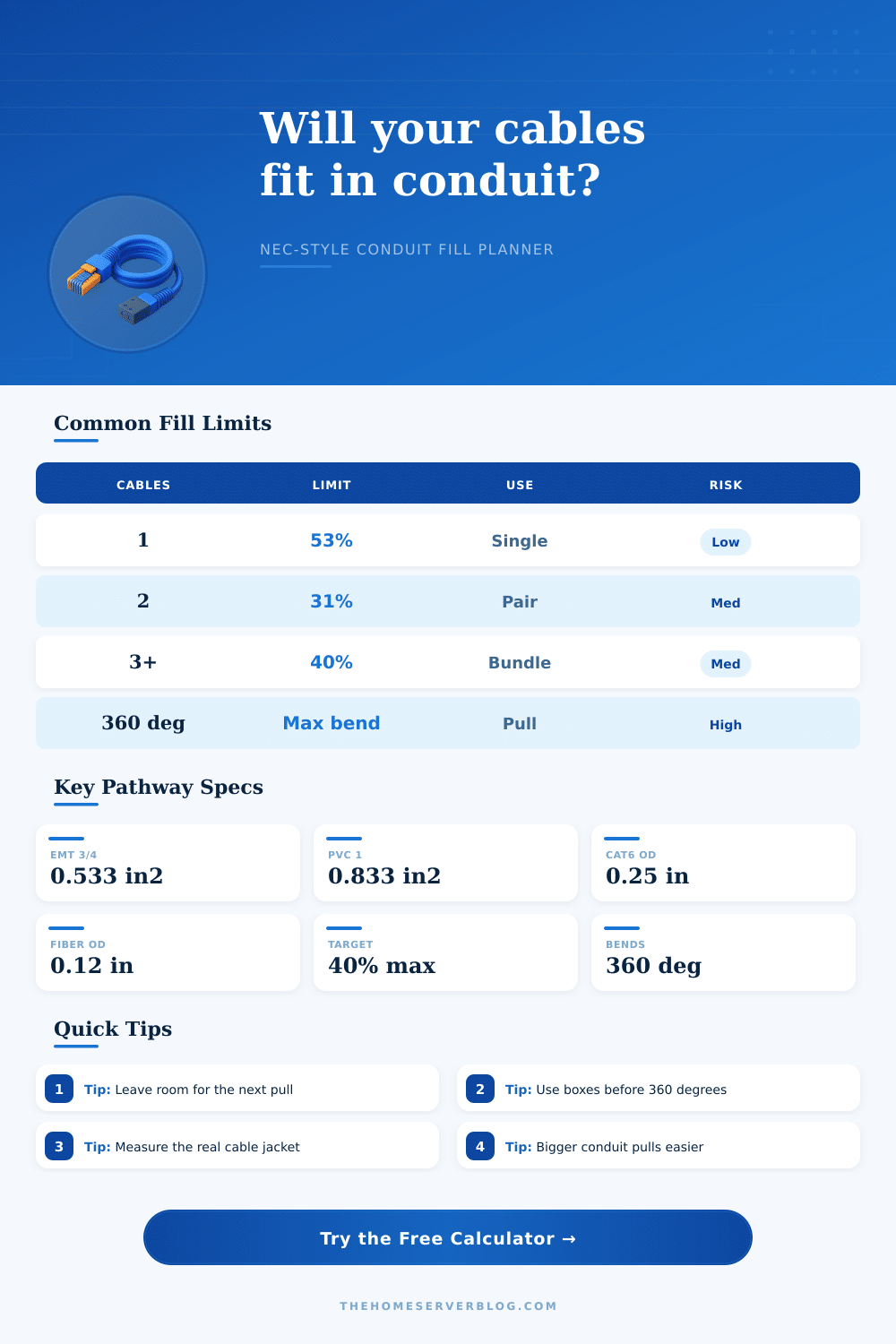
| Cable Count in Raceway | Common Fill Limit | Formula Used Here | Planning Meaning |
|---|---|---|---|
| 1 cable or conductor | 53% of conduit area | Conduit area x 0.53 | Useful for one large cable, but still plan bend radius and pulling grip. |
| 2 cables or conductors | 31% of conduit area | Conduit area x 0.31 | Lower allowance because two round objects jam more easily. |
| 3 or more cables | 40% of conduit area | Conduit area x 0.40 | Typical bundle planning rule for network, coax, fiber, and control cable groups. |
| Future pulls | Keep below limit | Allowed area minus target spare | A pathway that barely passes today can be difficult to reuse later. |
📐Conduit Trade Size Area Table
| Trade Size | EMT Area | PVC Sch 40 Area | Typical Home Lab Use |
|---|---|---|---|
| 1/2 inch | 0.304 in² | 0.285 in² | One or two small low-voltage cables with short, simple pulls. |
| 3/4 inch | 0.533 in² | 0.508 in² | Small Cat6 bundles, camera groups, and wall-to-rack drops. |
| 1 inch | 0.864 in² | 0.833 in² | Rack trunks, shop uplinks, coax mixes, and future spare capacity. |
| 1-1/4 inch | 1.496 in² | 1.453 in² | Large bundles or runs where a later cable pull is likely. |
| 1-1/2 inch | 2.036 in² | 1.986 in² | Dense pathways from utility rooms, racks, or media panels. |
| 2 inch | 3.356 in² | 3.291 in² | Main low-voltage sleeves between rooms, floors, or buildings. |
🖧Cable Outside Diameter Table
| Cable Preset | Typical OD | Area Per Cable | Best Planning Use |
|---|---|---|---|
| Cat5e UTP riser | 0.205 in | 0.033 in² | Light network drops and small PoE device groups. |
| Cat6 UTP riser | 0.250 in | 0.049 in² | Home server closets, APs, cameras, and desktop runs. |
| Cat6A shielded | 0.330 in | 0.086 in² | 10 GbE backbone pulls where cable diameter grows quickly. |
| RG6 coax | 0.275 in | 0.059 in² | Media panels, modem locations, MoCA, and antenna feeds. |
| 18/4 security cable | 0.180 in | 0.025 in² | Alarm, sensor, and low-current control circuits. |
| Indoor fiber cable | 0.120 in | 0.011 in² | Low-friction fiber paths with careful bend-radius planning. |
🛠Pull Planning Table
| Condition | Calculator Signal | Recommended Adjustment | Why It Matters |
|---|---|---|---|
| Fill under 30% | Usually easy | Keep sweep bends wide and label both ends. | Low fill leaves room for jacket friction and cable lay. |
| Fill 30% to 40% | Watch bends | Add an access box or move up one trade size. | Bundles can rotate, flatten, and drag near bends. |
| Over 270 degrees | Harder pull | Break the route into shorter pull sections. | Several bends stack friction even when fill is legal. |
| Over 360 degrees | Needs access | Add a pull point before continuing the route. | Many electrical raceway rules limit bends between pull points. |
💡Two Practical Tips
When you plan to run your cables through conduit, you must consider the physical difficulty of pulling those cables through a conduit. Running the cables through conduit isnt always easy due to the friction that the cables will encounter due to the jackets of the cables and the bends in the conduit. Additionally, you must allow for both the number of the cables and the amount of spare capacities that youll need for the future.
Beyond the size and the number of the cables that you plan to install, there are factors relate to the physical shape of the route that the conduit will take. For instance, a conduit that runs straight is going to allow for more fill with the cables than a conduit that has many bend. The more bends in the conduit, the more friction the cables will create as they are being pull through the conduit.
How to Plan Conduit Size and Cable Pulls
Therefore, the total length of the conduit and the total number of bend in the conduit are two factors that will impact the trade size of the conduit that you should consider when planning. An additional factor that you must consider for the conduit is the outside diameter of each of the cables that will be installed. The area that each cable will claim within the conduit is related to the outside diameter of the cable.
Therefore, it is critical that you use the actual diameter of each cable rather than guess at the dimensions of that cable. If you use an inaccurate diameter for the cables, your calculations may show that the cables will fit into the conduit, but they may not actualy fit into the conduit. One way of managing these measurements is through the use of a calculator.
Another consideration for conduit installations is the need to provide spare capacity for any future installation. Most people fail to provide enough spare capacity for future installations. For instance, a conduit that has thirty-nine percent of the capacity fill by the cables may be within specifications for the conduit, but it dont provide much flexibility for additional cables.
Ten or twenty percent of the conduit should be left empty to allow the individual who install the conduit in the future to easily add more cables to that conduit. Pull difficulty is a factor that can be more difficult to quantify then any other factor. Therefore, different style options for conduit installations will allow for different environments to be account for.
For example, if the conduit is going to run through an attic or a basement, the friction level will be different than if the conduit is remaining within an accessible wall. The style choice will affect the planning score for the conduit installation. The planning score will indicate the friction levels that will be encounter during installation.
Many people make mistake when planning the conduit installation. Many people will begin the installation process but then realize that the conduit size is too small for the number of bends in the conduit. To avoid this mistake, you should always begin with sketch out the conduit installation route.
After sketching the route, count the number of bends in the conduit. After determining the number of bends, estimate the length of the conduit. Finally, determine the conduit size that will allow for spare capacity for the future.
Reference tables can be used to ensure that the measurements for the conduit and the cables is correct. The trade sizes for conduit can vary depending on whether the conduit is metal or plastic. Additionally, the outside diameter of the cables can vary depending on the category of the electrical cables.
Using the reference tables will ensure that you use the correct measurements for conduit and cable size. Using incorrect measurements can lead to illegal electrical installation. If the planning calculator shows that the planning score is high or if there is a warning regarding the total bend angle of the conduit, some corrective action must be taken.
One corrective action is to add an accessible box to the conduit installation. This will reset the bend angle of the conduit. Additionally, an accessible box will allow the ejection of the cables should the cables begin to get stuck within the conduit.
Using an accessible box will make any future work on that conduit easy. Ultimately, conduit installations are perform to safely install the cables without damaging them and allow for time in the future for additional installations. While the conduit installation calculator will provide you with the numbers that you need to complete the installation, you must use your judgment to look at the entire route.
You must determine whether the numbers provided by the conduit installation calculator are enough to ensure a comfortable pull of the cables before you close the walls.