Patch Cable Length Calculator
Estimate rack patch lead length from source and destination U positions, horizontal and vertical managers, patch panel spacing, slack loops, bundle count, and bend radius.
⚙Named Rack Patching Presets
📏Rack and Cable Inputs
🧰Cable and Rack Spec Grid
📊Reference Tables
Cable and Bend Radius Planning
| Cable type | Typical OD | Common bend guide | Rack patch note |
|---|---|---|---|
| Cat5e UTP patch | 0.20 in | 4x OD | Good for light home lab patching. |
| Cat6 UTP patch | 0.24 in | 4x OD | General 1 GbE and short 10 GbE links. |
| Cat6A shielded | 0.30 in | 8x OD | Needs wider loops and more manager room. |
| Slim Cat6 | 0.15 in | 4x OD | Useful for dense 48-port switch faces. |
| Duplex fiber patch | 0.12 in | 10x OD | Preserve bend radius near trays and doors. |
| SFP DAC cable | 0.19 in | 10x OD | Round up when the cable is stiff. |
Standard Patch Cable Lengths
| Stock length | Metric approx | Best rack use | Watch point |
|---|---|---|---|
| 6 in to 1 ft | 0.15 to 0.3 m | Adjacent keystone or same-U patching | Little room for managers |
| 1.5 to 2 ft | 0.45 to 0.6 m | Panel to switch one or two U apart | Check port side offset |
| 3 to 5 ft | 0.9 to 1.5 m | Horizontal manager dress paths | Avoid large front loops |
| 7 to 10 ft | 2.1 to 3.0 m | Vertical managers in half racks | Bundle and label carefully |
| 12 to 20 ft | 3.7 to 6.1 m | Full-rack drops or overhead paths | Support cable weight |
Manager Routing Allowances
| Route style | Added shape | Best for | Planning caution |
|---|---|---|---|
| Direct front patch | Shortest face path | Adjacent ports and lab benches | Can look messy in dense panels |
| Horizontal manager | D-ring or brush pass | Panel-to-switch pairs | Add length for each manager crossed |
| Vertical side manager | Side travel plus re-entry | Large U gaps and full racks | Needs side-to-port reach |
| Overhead ladder | Up, across, and down | Rack-to-rack or top patch paths | Secure and label both ends |
Common Rack Patching Projects
| Project | Typical bundle | Starting length | Secondary check |
|---|---|---|---|
| 1U patch panel to 1U switch | 24 cables | 1 to 2 ft | Port side alignment |
| Top-of-rack switching | 24 to 48 cables | 2 to 3 ft | Horizontal manager fill |
| Half rack vertical patch | 12 to 36 cables | 5 to 7 ft | Slack loop placement |
| 42U cross-rack service loop | 24 to 48 cables | 7 to 12 ft | Bend radius at side manager |
| Fiber uplink pair | 2 to 12 cables | 3 to 10 ft | Door swing and radius |
✅Two Practical Tips
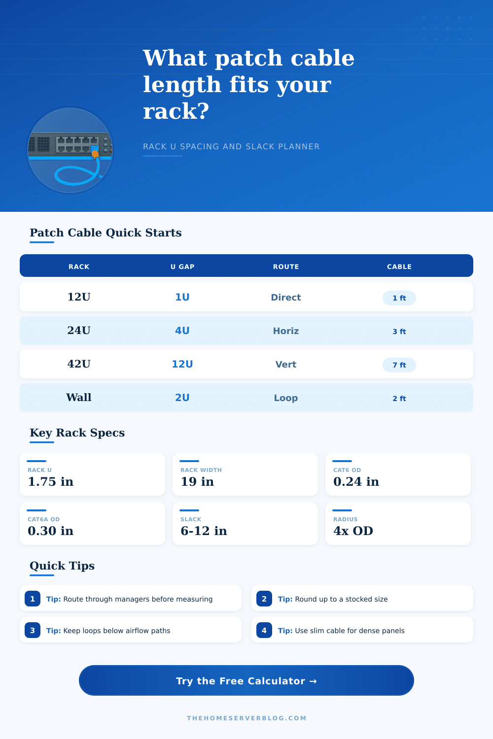
When you determine the lengths of patch cables to order for a server rack, you must take into account the path that the patch cable will travel. A person may measure the vertical distance from the patch panel to the switch, but the vertical distance are not the same as the distance that the patch cable will travel. A patch cable that is too short will not be able to reach the destination ports, and a patch cable that is too long may obstruct the airflow from the server rack or hide the labels on the patch panel itself.
A server rack is measured in rack units. Each rack unit correspond to a certain vertical distance within the rack. The vertical distance from the patch panel to the switch indicates the baseline length for the patch cable, but does not account for the distance that the patch cable will travel within the rack.
How to Measure Patch Cable Lengths for a Server Rack
Patch cables typically exit a patch panel, enter a cable manager, turn at a corner within the rack, and enter a switch. Each of these turns and managers adds to the length of the patch cable. There are horizontal managers that sits between the different rows of network equipment, and vertical managers that run down the sides of the server rack.
Managers allow patch cables to move horizontal or vertically within the rack. Each time a patch cable enters and exits a manager, the patch cable must travel a longer distance within the rack than if it traveled in a more direct fashion. Thus, the more managers that a patch cable travels, the longer the patch cable required to cover such a distance within the rack.
The position of the port to which a patch cable is plugged also play a role in the length of the patch cable. A patch cable that is plugged into the far left side of a patch panel will have to travel a longer distance horizontal than a patch cable that is plugged into a port in the center of the panel. This horizontal distance must be added to the vertical distance within the rack to determine the total distance that the patch cable will travel.
Finally, the distance between the end of the patch cable and the rack rail must also be accounted for. Another variable that affect the length of a patch cable is slack. Slack is the extra length of a patch cable that hangs in a loop at the end of the patch cable.
A technician uses slack to allow the technician to pull the patch panel forward to service the rack, or to allow for rerouting of a patch cable to a different location within the rack. If slack is not accounted for in the length of the patch cable, the patch cable may be too short to permit such movement. All patch cables have a bend radius.
The bend radius is the maximum distance to which the patch cable can be bent. If a patch cable is bent to a radius that is too sharp, the copper (for copper cables) or the fiber (for fiber optic cables) can be damaged. Such damage to the patch cable can lead to poor signal quality from the patch cable.
The bend radius is calculated from the outer diameter of the patch cable. Thus, the length of the patch cable must account for the bend radius to allow for the cable to make turns in the rack that are not too sharp. The bundle size for patch cables also has an impact on the length of the patch cable required.
Patch cables that are grouped together in a bundle will have the patch cables on the outside of the bundle travel a longer distance than the patch cables on the inside of the bundle. Thus, large bundles of patch cables take up more space within a cable manager, and those patch cables may have to bend more sharply around other patch cables within that bundle if the manager is too small to allow the patch cables to travel to their destination. Not all patch cables are created the same.
For example, standard Cat6 patch cables are the most common type, but shielded Cat6A patch cables are thicker than Cat6 cables. Consequently, Cat6A patch cables require more length to allow for the cables to make gentler bends around corners in the rack. Additionally, the bend radius for fiber optic and direct-attach patch cables is more restrictive than for copper patch cables.
Thus, you should decide the type of patch cable before the technician calculates the length of the patch cable. These variables must be accounted for before ordering patch cables. The manufacturer typically makes patch cables available in standard lengths.
If the length of the patch cable is calculated to be somewhere in the middle of two standard lengths, the next largest length should be ordered to allow slack for the patch cable to hang in a loop at the end of the patch cable. Some of the most common mistake when calculating the length of patch cables is to only calculate the vertical distance between the rack units from which the patch cable will emerge from the switch panel to the destination switch. Other common mistakes is to forget the horizontal distance between ports or to forget to account for the length of the cable managers.
These mistakes will result in the patch cables being either too short or too long to allow for proper airflow within the rack. To avoid these mistakes, the technician should calculate the length of the patch cables by taking into account each of these individual variables. The distance from each rack unit, the horizontal distance between the ports, the length required for each cable manager, the slack for the patch cable, the bend radius of the patch cable, and the bundle size of the patch cables should all be accounted for when calculating the total length of patch cable that will be required.
Once this length is calculated, a standard length of patch cable can be selected from the manufacturer. By following these steps, the technician will be certain that the patch cables are of the correct length for the task.