Cable Tray Weight Calculator
Estimate cable tray dead load, fill area, support reaction, and safety margin for home labs, studios, workshops, and light infrastructure runs.
Cable weights and diameters are planning values. Use manufacturer data sheets for final structural and electrical design.
Calculation Breakdown
| Cable type | Planning diameter | Weight | Typical use |
|---|---|---|---|
| CAT6A UTP | 0.30 in | 35 lb / 1000 ft | Server, switch, AP links |
| Duplex fiber | 0.12 in | 10 lb / 1000 ft | Backbone and uplinks |
| RG6 coax | 0.28 in | 33 lb / 1000 ft | Camera, antenna, AV |
| 12/3 MC cable | 0.48 in | 145 lb / 1000 ft | Branch circuits |
| 10 AWG feeder | 0.58 in | 260 lb / 1000 ft | Higher power drops |
| Spare future cable | 0.30 in | 35 lb / 1000 ft | Reserved capacity |
| Tray material | Base weight model | Best fit | Planning note |
|---|---|---|---|
| Aluminum light ladder | 0.90 + 0.055 lb/ft per in | Home lab runs | Lower dead load, easy handling |
| Aluminum medium ladder | 1.35 + 0.070 lb/ft per in | Rack aisles | Good balance of load and span |
| Galvanized steel | 1.80 + 0.115 lb/ft per in | Workshop power | Heavier but sturdy |
| Heavy steel ladder | 2.60 + 0.160 lb/ft per in | Dense power bundles | Check anchors closely |
| Wire mesh basket | 0.70 + 0.045 lb/ft per in | Data cable paths | Great for low voltage moves |
| Fiberglass FRP | 1.60 + 0.095 lb/ft per in | Corrosive areas | Confirm temperature rating |
| NEMA style class | Uniform load | Span basis | Calculator comparison |
|---|---|---|---|
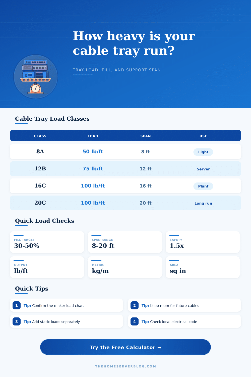
| 8A | 50 lb/ft | 8 ft | Light data and controls |
| 12A | 50 lb/ft | 12 ft | Longer light support spacing |
| 12B | 75 lb/ft | 12 ft | Mixed low voltage and power |
| 16B | 75 lb/ft | 16 ft | Medium infrastructure runs |
| 20C | 100 lb/ft | 20 ft | Heavy long span planning |
| Scenario | Tray size | Common load driver | Watch point |
|---|---|---|---|
| Small Home Lab 12U | 6 x 2 in | Patch cable density | Leave slack near rack |
| PoE Camera Run | 8 x 2 in | Long CAT6A bundles | Do not crush bends |
| Full Rack Overhead | 18 x 4 in | Data and power separation | Support over rack row |
| Garage Workshop Power | 12 x 4 in | MC and feeder weight | Confirm anchors in structure |
| Studio Hybrid Cabling | 12 x 3 in | AV plus data bundles | Plan cable grouping |
Cable tray weight planning is a necessary process to prevent the support from bowing and the cables from sagging between the supports. Many people building small laboratories or workshops may assume that the weight of the tray and the cables will be very light. However, the actual weight of the tray and the cables can be more higher than the people expect.
The weight estimate has to be calculated prior to mounting any tray to the ceiling to make sure that the support bracket can hold the tray and the cables. The calculator require the user to input information regarding the width of the tray, depth of the tray, the number of cables that will be installed, and the distance between supports. The width and depth of the tray will determine the size of the tray and the number of cables that can be accommodated.
How to Plan Cable Tray Weight and Supports
The number of cables determine the weight of the tray. The distance between the supports will impact the reaction force of each support bracket. The calculator output the total weight of the installation, the uniform load that the tray and supports will carry each day, the reaction of each support, the amount of space left in the tray for additional cables, and whether the installation allow for proper heat dissipation from the equipment that will be installed on the tray.
These outputs allow the installer to compare the load calculations of the installation to the load classes of the tray supports so that they can avoid memorizing the load table. The material from which the tray is made will impact its behavior under the load of the tray and its cables. Aluminum trays will have less dead load than steel trays.
However, aluminum trays will flex under heavy loads compared to steel trays. Steel trays can span further than aluminum trays without sagging. However, the weight of the tray will reduce the amount of load that the tray can carry.
Wire basket trays will also have less tray weight than solid trays. Furthermore, wire basket allow for increased airflow over the tray. Solid trays will provide more protection of the items on the tray but will have more tray weight and less fill margin for the cables.
These differences are accounted for in the tray weight calculator. Most installations will include more than one type of cable. A security installation, for example, may include both light CAT6A and heavy coaxial cables.
A workshop installation will have fewer but heavier MC power cables. There are different cable profile within the calculator to which you can switch to account for different types of cables in your installation. The static load input allow you to account for items that are not cables that will be on the tray.
A safety factor has to be included to account for any error in the planning process. Most installations use a safety factor of 1.5 to account for potential errors in the weight of the cables and to account for additional cables that may be added to the tray during installation. A higher safety factor is required for installations that pass over occupied area or if the inspectors requires a higher safety factor.
This safety factor can be applied to both the uniform load and the support reaction load. Common mistakes are made during installation. One of the most common is placing supports at the maximum distance without checking if the weight of the cables will fall within the load class of the tray supports.
Tray fill percentage is also often mistaken for a hard limit; the percentage is merely a suggestion for installation. People often do not consider the weight of the tray itself. A wider tray will allow for more cables but will create a higher uniform load on the tray supports before any cables are installed.
The reference table provide typical weights for the cables and tray base model that are available. The load tables use the NEMA load classes to make it easier to understand the results of the tray weight calculator for people who are used to using these load classes. These tables is a starting point for planning the installation but do not replace a full structural engineering review of the installation.
Once the tray weight estimate is made, there are a few additional step to completing the installation. You must ensure the anchor size to match the reaction load of each support bracket calculated in the tray weight calculator. Additionally, the cable separation rule must be checked to ensure they are met within the fill margin of the tray.
Finally, there should be a margin for additional cables that may be added during installation. All the calculations are based off the initial estimate of the number of cables; the tray will remain level and the supports will be able to handle the load.