Fiber Attenuation Calculator
Estimate passive optical attenuation from fiber type, wavelength, distance, connectors, splices, bend events, and reserve margin for home lab and small site fiber runs.
| Fiber category | Wavelength | Typical attenuation used | Planning note |
|---|---|---|---|
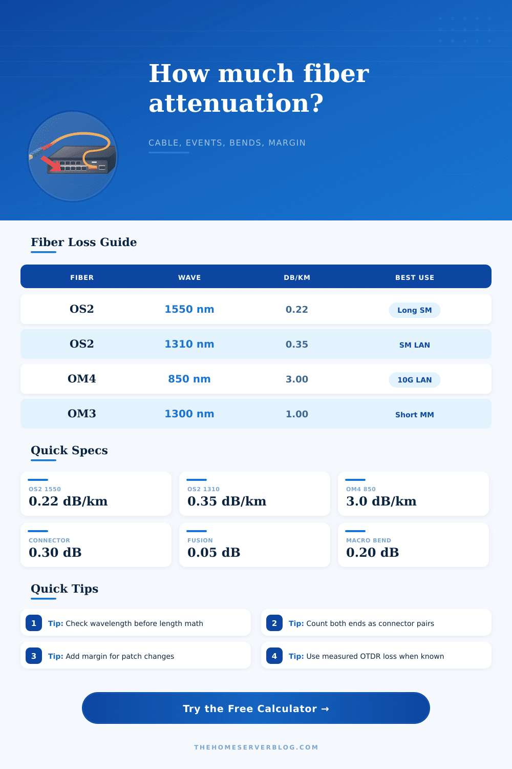
| OS2 single-mode | 1310 nm | 0.35 dB/km | Common short-to-medium single-mode LAN planning value. |
| OS2 single-mode | 1550 nm | 0.22 dB/km | Lower fiber loss for longer passive runs. |
| G.657 bend-insensitive single-mode | 1310 nm | 0.35 dB/km | Use when small cabinets or wall boxes create bend risk. |
| G.657 bend-insensitive single-mode | 1550 nm | 0.22 dB/km | Same length math, usually less macro-bend penalty. |
| OM1 multimode | 850 nm | 3.50 dB/km | Legacy short runs; distance limits often matter before loss. |
| OM1 multimode | 1300 nm | 1.50 dB/km | Used by older multimode optics and media converters. |
| OM3 multimode | 850 nm | 3.00 dB/km | Common 10G SR assumption for structured cabling. |
| OM4 multimode | 850 nm | 3.00 dB/km | Similar attenuation to OM3 with better bandwidth distance. |
| OM3 or OM4 multimode | 1300 nm | 1.00 dB/km | Useful for some legacy 1G and specialty optics. |
| OM5 wideband multimode | 850 nm | 3.00 dB/km | Planning is close to OM4 for ordinary 850 nm links. |
| Event type | Calculator default | Conservative range | When to override |
|---|---|---|---|
| Clean mated connector pair | 0.30 dB | 0.20 to 0.50 dB | Use test-set readings for field-terminated or older connectors. |
| Fusion splice | 0.05 dB | 0.03 to 0.10 dB | Raise it for field repairs, closures, or questionable splice quality. |
| Mechanical splice | 0.20 dB | 0.10 to 0.50 dB | Enter a higher splice loss when quick mechanical joints are used. |
| Cabinet bend or tight loop | 0.10 dB | 0.05 to 0.50 dB | Increase for small wall boxes, zip ties, or non-bend-insensitive fiber. |
| Patch changes and cleaning drift | 0.50 dB | 0.20 to 1.00 dB | Add allowance when patch panels will be moved over time. |
| Named fiber run preset | Fiber and wavelength | Typical distance | Why the preset exists |
|---|---|---|---|
| ONT to Rack | OS2 1310 nm | 25 m | Short indoor run with two patch locations and low fiber loss. |
| Switch Trunk | OM4 850 nm | 65 m | Typical in-home 10G SR trunk between network closets. |
| Garage 10G | OM3 850 nm | 90 m | Multimode link where connector events dominate distance loss. |
| Detached Office | OS2 1310 nm | 120 m | Outbuilding single-mode run with splices and cabinet bends. |
| Camera Pole | OS2 1310 nm | 180 m | Outdoor conduit or pole run with repair allowance. |
| Aerial Drop | G.657 1550 nm | 250 m | Bend-insensitive fiber for drop loops and small enclosures. |
| Campus Link | OS2 1550 nm | 1.2 km | Small site backbone where cable attenuation is visible. |
| MPO Rack Row | OM4 850 nm | 35 m | Short dense patching with several mated connector pairs. |
| Lab Bench | OM3 850 nm | 12 m | Short test lead where dirty or reused connectors matter most. |
| Long OS2 Run | OS2 1550 nm | 4 km | Longer passive path for checking total attenuation trend. |
| Planning check | Formula | Best input source | Practical use |
|---|---|---|---|
| Fiber loss | Length km × dB/km | Cable datasheet or standard class | Shows whether distance is a meaningful part of the path. |
| Connector loss | Pairs × pair loss | Inspection, test set, connector grade | Usually the largest term in short home lab runs. |
| Splice loss | Splices × splice loss | Splice machine estimate or OTDR | Captures closures, repairs, and pigtail transitions. |
| Bend loss | Events × event loss | Tray layout and bend radius review | Highlights avoidable cabinet and wall-box penalties. |
| Design attenuation | Total + margin + aging | Local operating practice | Gives a stable planning number before optical power checks. |
Fiber optic cable loss is often caused by factor other than the length of the fiber optic cable. While distance is thought to be the most important factor in fiber optics, there is many factors that cause a fiber optic cable to lose more of its signal than the glass within the cable itself. Before installing a fiber optic cable, it is important to perform a calculation to ensure that the fiber optic cable wont experience problems like dropped frames or slow connection speeds.
Inputs into the calculator will include the length of the fiber optic cable and the type of fiber optic cable that will be used. In addition to these two factors, additional inputs will include the number of connector pair and the number of splices that will be used within the fiber optic cable run. Each mated connector pair will create approximately 0.3 decibels of loss.
How to Calculate Fiber Optic Cable Loss
The loss can be increased if the connectors is known to be dusty or if individuals in the field have handled them. Fusion splices will contribute 0.05 decibels of loss. However, mechanical splices will contribute more loss to the signal then fusion splices.
Bends in the fiber optic cable will also lead to signal loss; a tight service loop or a tight bend within a wall box will contribute 0.1 decibels of loss to the signal. Each of these factors will contribute to the total loss within the fiber optic cable run. The calculator will output the total passive loss of the fiber optic cable run.
Additionally, the calculator will calculate the total loss of the system including a chosen margin. This total loss is compared to the maximum loss that the network plan or the optics can sustain. If the total loss including the margin is lower then the target loss, then there is time to make future changes to the fiber optic cable or to change patch cords.
However, if the total loss is higher than the target loss, the fiber optic cable will have to be shortened, the number of connections within the system will have to be reduced, or the user will have to change the type of fiber optic cable. The margin is not an optional selection. The margin is used to protect the connection from issues like the aging of the patch cords or the replugging of the optical fiber connectors.
An aging allowance is requested within the calculator because these connections will slowly degrade in relation to the fiber optic cable loss. If the aging allowance is left at 0, the system may appear to be efficient when it is installed, but it may become expensive due to the need to replace the optical fiber cable run. The tables within the calculator illustrate the attenuation rates for different categories of fiber optic cable at different wavelengths.
For instance, single mode fiber optic cables lose 0.22 decibels per kilometer at 1550 nanometers, but lose 0.35 decibels per kilometer at 1310 nanometers. Additionally, multimode fiber optic cables lose 3 decibels per kilometer at 850 nanometers. These attenuation rates are important to consider for very long distances between the optical transmitter and the optical receiver.
However, they are less important for short distances between the optical transmitter and the optical receiver. The tables can help to establish the default settings for connector and splice loss. Many people make error in counting the number of connectors.
For instance, there may be two connector pairs for every installation between the racks in a data center; the signal must pass through both of these pairs. This is accounted for within the calculator so that the calculations remains accurate. Additionally, there may be issues with the cleanliness of the connectors.
Dirty connectors can contribute to the loss of 0.1 decibels of optical power. A dropdown menu allow the optical installers to choose the cleanliness of the connectors. The optical fiber cable loss calculator will convert the units of the distance of the optical fiber cable.
For instance, the distance can be entered in meters, feet, kilometers or miles. After the conversion of the distance units, the calculator will multiply the distance by the attenuation rate of the fiber optic cable to determine the loss of optical power that will occur due to the fiber optic cable alone. The losses due to the connectors, the splices and the bends in the fiber optic cable can be added to this value to determine the total loss.
This total loss can be displayed in a breakdown section that displays the loss of the fiber optic cable alone and the loss of the connectors, splices and bends. This breakdown can help to determine where the excess loss is coming from. For very short distances between the optical fiber transmitter and the optical fiber receiver, the loss of the fiber optic cable will be very low.
For instance, a twenty meter OS2 fiber optic cable will lose 0.007 decibels of optical power at 1310 nanometers. Additionally, an OM3 fiber optic cable of the same length will lose 0.06 decibels of optical power at 850 nanometers. In these instances, the loss comes from the connectors and the bends in the cable, not the fiber optic cable.
This information can help the optical fiber cable installer to focus on the number of patch cords that will be used rather than on the quality of the fiber optic cable that is purchased. For long distances between the optical fiber transmitter and the optical fiber receiver, the loss of the fiber optic cable will be the major contributor of loss. The attenuation rates will become more important in these instances; it may be beneficial to use single mode fiber optic cable at 1550 nanometers rather than at 1310 nanometers, or it may be beneficial to use a bend-insensitive fiber optic cable if the path of the cable includes many bend.
There are preset buttons for these settings on the calculator so that a technician can instantly load settings that is realistic for a fiber optic installation. By performing the calculation of optical fiber cable loss before the ordering of the fiber optic cable or before the fiber optic cable is pulled, the fiber optic cable designer or installer can avoid issues after the installation of the fiber optic cable in the wall. Such a calculation of loss is simple arithmetic; however, it is beneficial to performing such calculations prior to the installation of the fiber optic cable.
The fiber optic cable itself is only one part of the total communication system; the balance of the system is accounted for in the calculation so that the total loss is easily predictable.