Three-phase Power Calculator
Estimate real power, apparent power, reactive power, breaker margin, heat output, and phase balance for three-phase panels, motors, UPS gear, and dense home lab racks.
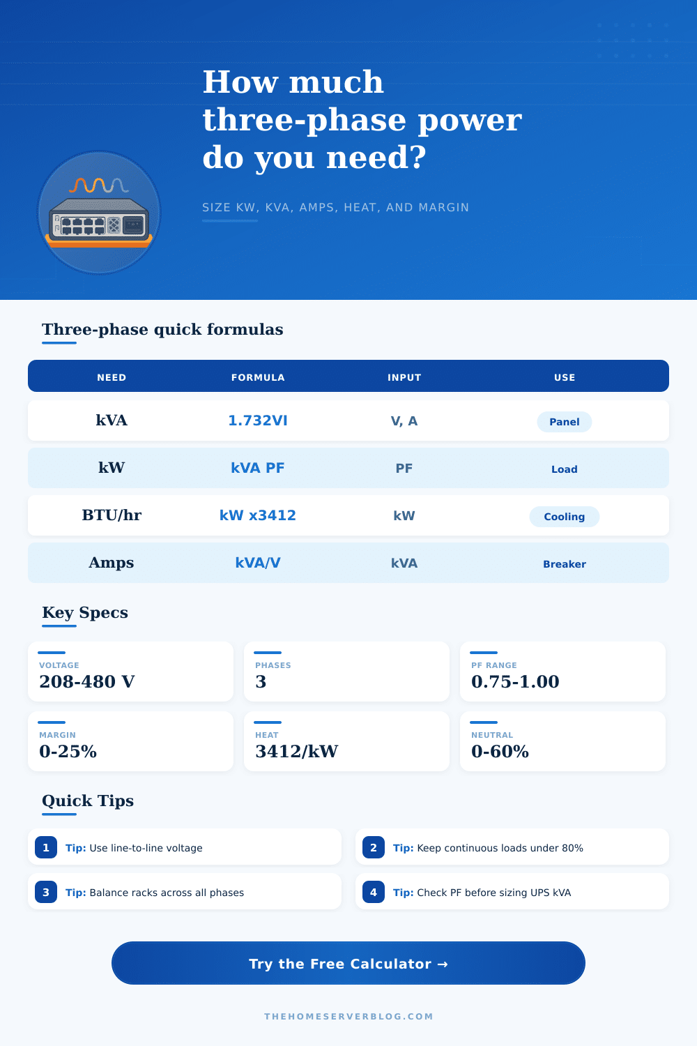
| Need | Formula | What to enter | Practical use |
|---|---|---|---|
| Apparent power | kVA = 1.732 x VLL x A / 1000 | Line voltage and line current | UPS, transformer, generator, and feeder sizing |
| Real power | kW = kVA x power factor | Power factor from meter or nameplate | Actual electrical work and heat-producing load |
| Reactive power | kVAR = square root of kVA squared minus kW squared | Calculated from kVA and kW | Motor and transformer load quality checks |
| Heat load | BTU/hr = kW input x 3412 | Real input power | Cooling estimate for closets and server rooms |
| Profile | Typical power factor | Efficiency range | Best sizing target |
|---|---|---|---|
| Rack PDU / IT load | 0.92 to 0.99 | 90 to 96 percent | Keep continuous branch load near 80 percent |
| Online UPS input | 0.95 to 1.00 | 92 to 97 percent | Size by kVA and battery charger recovery current |
| Induction motor | 0.78 to 0.88 | 82 to 94 percent | Allow starting current outside this steady-state estimate |
| EVSE or charger stack | 0.97 to 1.00 | 92 to 96 percent | Treat long charging sessions as continuous load |
| Service | 20 A apparent power | 80 percent continuous | Typical home lab fit |
|---|---|---|---|
| 208 V three-phase | 7.2 kVA | 5.8 kVA | Dense rack PDU, UPS input, lab subpanel |
| 240 V three-phase delta | 8.3 kVA | 6.6 kVA | Workshop equipment and mixed motor loads |
| 400 V three-phase | 13.9 kVA | 11.1 kVA | International rack and UPS distribution |
| 480 V three-phase | 16.6 kVA | 13.3 kVA | Larger mechanical, EVSE, or facility loads |
| Scenario | Typical input | Watch item | Planning note |
|---|---|---|---|
| Metered rack PDU | 208 V, 16 to 24 A | Breaker margin | Use real meter current instead of nameplate total |
| UPS-backed server rack | 208 V, 10 kVA class | kVA versus kW | UPS capacity is constrained by both apparent and real power |
| Motor-driven compressor | 240 V, lower PF | Starting current | This calculator estimates running load, not inrush |
| Small server room | 208 V, 30 to 60 A | Heat removal | BTU/hr is usually the first room constraint |
Pull a rack into your garage server room and plug it in. It’s got lights on. But then the breaker go. Oh no, you look at the name plate: it says 20 Amps per phase; nothing to worry about! Wrong. Where most people make mistake here is that the name plate shows you the max amount of current that the device will accept, not how much current your device are taking off the wall.
Single-phase outlets in your house work different than three-phase power; assuming it’s just a matter of adding up numbers will result in burnt hot wires and tripping breakers. The calculator do all this math for you if you plug in your current and voltage, relieving you from having to guess at the numbers yourself.
Why You Must Calculate Power Correctly
What’s confusing people most often is that they don’t know the difference between apparent power and real power. The latter is the stuff which really works, cooling a processor or spinning a fan. The former also contains the reactive part of the load, which move around and back, not doing any useful work. You enter this number into calculator as power factor. Older UPS systems and induction motors causes that number to drop. To get the same amount of actual (real) power, you have to send more amps. It’s a little thing, but when you’re sizing breakers, it matters.
“Maybe they’re thinking that you’re only pulling five kilowatts. But with a poor power factor, their meter shows them an apparent load that’s much higher, and it’ll heat up your conductors whether the energy is bouncing around or actualy doing any work.”
Of course, then there’s the heating issue. Each watt entering your rack eventually become heat exiting the rack. Here, the formula use the normal conversion between watts and BTUs. This helps when you plan the room. Many people overestimate how many watts a given rack can hold, but they underestimate just how much air-cooling a densely-packed rack of servers demand. Twenty kilowatts may sound reasonable; until you learn that it produce almost seventy thousand BTUs per hour. That’s about as much cooling as opening all the windows in high summer. Without factoring in this thermal output, your gear will turn itself off or throttle back to prevent overheating.
The table near the bottom of the page explain it all: How much capacity you get varies depending on what voltage you choose. Lower voltages such as two hundred V carry less current then higher ones (e.g., 480V), so with same amount of power, you’ll use thinner wires.
There’s also something called Phase Balance which is a silent killer. In a three-phase system, each leg must carries its fair share of the load. Running heavy equipment on just two legs create imbalance. This imbalance causes higher losses and strains transformers. To calculate this risk, the calculator will ask you to enter “line current per phase.” For example, in a home lab, this means not having your high-draw servers stacked onto one leg because it’s convenient, spread them out between all three phases. Balanced loads lasts longer and run cooler.
Last but certainly not least: Margin! Spikes in electricity aren’t good. Adding an overhead percentage to the calculation as part of your design is easy with the tool. A 10% buffer is sufficient for both measurement error and growth. Most nameplates reflect their peak performance, not typical usage levels. Use a meter to measure what you actualy pull. Reading the sticker on the side of the case will get you a better baseline. Add a little more overhead so that upgrading your power supply or adding another drive bay doesn’t immediately overload the circuit.
It should of been about risk management, not simply getting things to fit in the slots. Measure what’s actualy running. Include a buffer for the future. Confirm you’ve accounted for the thermal output so your equipment don’t throttle or shut down. Check if your room can handle the heat before you worry about whether it fits in the rack. Physical reality, air moving, wires connecting, dictates how it looks. The numbers tell you where to go; the real world determines the end result.
You brought that rack into the garage because you want reliability. Half the battle is ensuring the power infrastructure can support it. Balance the phases, consider the heat load, and your system will run as cool and stable as you intended.