Signal budget calculator
dB Loss Calculator
Estimate signal loss through coax, Wi-Fi paths, fiber jumpers, splitters, adapters, and home lab RF runs using length, frequency, connector count, insertion loss, and margin.
▣ Signal loss presets
⚙ Link and cable inputs
Full signal loss breakdown
▦ Equipment and media comparison grid
RG-58 Coax
Useful for short bench jumpers, handheld radios, and low-power tests where routing is more important than efficiency.
RG-6 Coax
Common for CATV, MoCA, satellite IF, and OTA TV runs with F connectors and splitter networks.
LMR-240 Coax
Good middle-ground coax for Wi-Fi antennas, LoRa gateways, scanner feeds, and compact outdoor routes.
LMR-400 Coax
Lower-loss choice for long home lab RF feeds, base antennas, cellular boosters, and remote radio heads.
Cat6 Channel
Insertion loss is part of structured cabling certification; stay within 100 m channel length for Ethernet.
OM3 Fiber
Short-reach 10G multimode links often have low distance loss but still depend on clean LC pairs.
OS2 Fiber
Single-mode fiber has very low cable loss, so connectors, splices, and transceiver budgets usually dominate.
Adapter Pair
A tiny adapter loss matters when repeated through patch panels, wall plates, arrestors, and coupler stacks.
▤ Cable attenuation reference
| Media type | Reference point | Typical attenuation | Practical use |
|---|---|---|---|
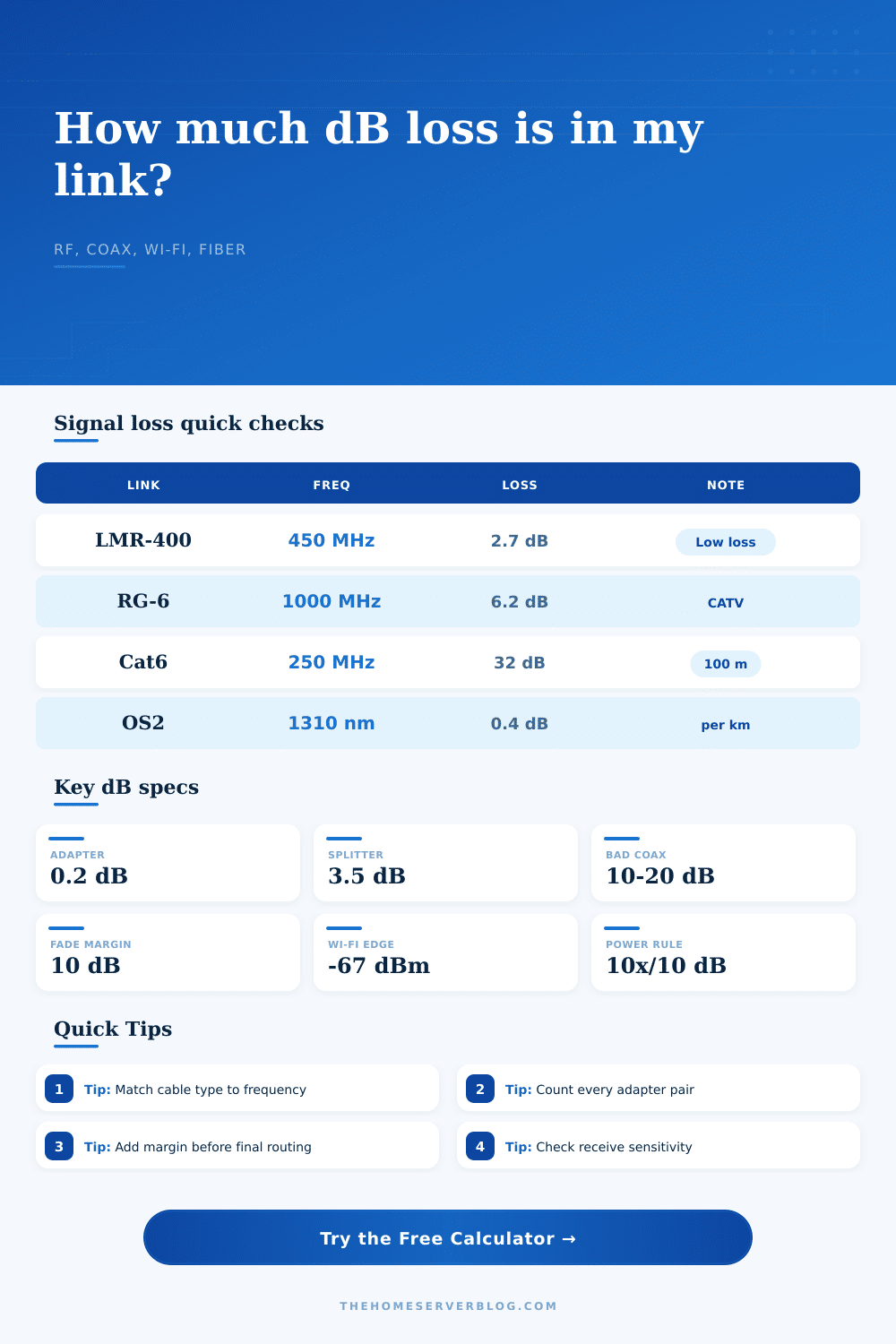
| RG-58 coax | 900 MHz, 100 ft | About 10.6 dB | Short jumpers, scanners, temporary RF tests |
| RG-6 coax | 1000 MHz, 100 ft | About 6.2 dB | TV, MoCA, satellite IF, OTA distribution |
| RG-8X coax | 900 MHz, 100 ft | About 8.5 dB | Portable HF/VHF, moderate home antenna runs |
| LMR-240 coax | 2400 MHz, 100 ft | About 7.6 dB | Wi-Fi antennas, LoRa gateways, compact RF links |
| LMR-400 coax | 2400 MHz, 100 ft | About 6.6 dB | Longer RF feeds where loss must stay controlled |
| Cat6 channel | 250 MHz, 100 m | About 32.8 dB | Structured Ethernet certification and channel checks |
| OM3 fiber | 850 nm, 1 km | About 3.5 dB | Short-reach multimode SFP/SFP+ links |
| OS2 fiber | 1310 nm, 1 km | About 0.4 dB | Single-mode backbones and long home campus runs |
▥ Passive component loss table
| Component | Typical dB loss | Where it appears | Calculation note |
|---|---|---|---|
| Clean RF connector pair | 0.1 to 0.3 dB | N, SMA, BNC, F, LC, SC pairs | Count every mated pair, not every loose connector |
| Mixed adapter stack | 0.5 to 0.75 dB | Gender changers and emergency adapters | Use higher loss when the adapter is old or unknown |
| 2-way splitter | 3.5 to 4.0 dB | CATV, OTA TV, MoCA branches | Each split roughly halves the power plus internal loss |
| 4-way splitter | 7.0 to 8.0 dB | Distribution panels and amplifier outputs | Use the marked port value when available |
| 8-way splitter | 10.5 to 12 dB | Large coax distribution panels | Often needs amplification or shorter downstream runs |
| Lightning arrestor | 0.2 to 1.0 dB | Outdoor antenna entry points | Add as extra insertion loss if not known exactly |
| Fiber splice | 0.05 to 0.3 dB | Fusion or mechanical splice trays | Connector cleanliness can outweigh short fiber distance |
| Fixed attenuator pad | 3 to 20 dB | Receiver protection or level balancing | Enter the marked pad value as passive device loss |
▧ Signal level and dB meaning
| dB change | Power ratio | Voltage ratio | Practical meaning |
|---|---|---|---|
| 1 dB loss | 79.4% remains | 89.1% remains | Small but measurable in a tight budget |
| 3 dB loss | 50.1% remains | 70.8% remains | Roughly half the power |
| 6 dB loss | 25.1% remains | 50.1% remains | One quarter of the power remains |
| 10 dB loss | 10.0% remains | 31.6% remains | One tenth of the power remains |
| 20 dB loss | 1.0% remains | 10.0% remains | Large attenuation; check gain or shorter cable |
| -67 dBm Wi-Fi | Target level | Service design | Common minimum for reliable high-rate client use |
| -90 dBm LoRa | Still usable | Low data rate | Many LoRa links tolerate far weaker signals |
| 0 dBm | 1 milliwatt | Reference level | dBm is an absolute power level, not a loss value |
▨ Common home lab signal budgets
| Project | Typical input | Loss target | Planning note |
|---|---|---|---|
| Outdoor ham antenna feed | 30 to 50 dBm transmitter | Under 3 dB if possible | Long VHF/UHF runs benefit from LMR-400 or better |
| MoCA coax backbone | Adapter-managed level | Keep splitters low | Unneeded 4-way and 8-way splitters are common loss sources |
| 5 GHz bridge | 10 to 23 dBm radio | Leave 10 dB margin | Path and antenna gain often matter more than coax length |
| Cellular booster donor antenna | Weak outdoor service | Minimize feed loss | Mount the booster close to the antenna when cable loss is high |
| 10G multimode patch | SFP+ optical budget | Usually under 2 dB | Clean connectors and correct fiber type are the main checks |
| Cat6 permanent link | Ethernet PHY budget | Follow 100 m limit | Insertion loss rises with frequency and cable length |
| ADS-B receiver feed | Very weak aircraft signals | Short low-loss coax | Place the low-noise amplifier near the antenna when used |
| Satellite IF distribution | LNB output over RG-6 | Compensate long runs | High-frequency IF loss can be larger than expected |
ℹ Practical calculation tips
Maybe you run some wires up your house to the attic or put in an outdoor antenna. Maybe you fuss and fiddle with connector pieces that don’t fit just right, but when you fire up your receiver or radio, all you get is static. Your antenna and cables are good; they survived the trip from point A to B, but somewhere along the way, the signal went down for dead.
Decibels of loss eliminates that aggravation. It transforms a guessing match into a pre-cut-the-wire budget. I know it all sounds confusing but the math is simple. Power values don’t work well with multiplication. However, subtraction and addition work fine because decibels aren’t an absolute unit of measurement; they’re a ratio.
Why Signals Get Weaker
Half of your power are a 3 dB loss. One tenth of your power is a 10 dB drop. You can use the calculator to plug in the numbers, but knowing where those numbers come from helps keep your link strong.
How many have underestimated just how fast small losses compound? A slightly dirty connector pair might only cost you a tenth of a decibel, but if you have three adapters, those tenths adds up. And then there’s a couple of splitter stages and a long run of cable. Those tenths will add up pretty quick and create a gap that the receiver simply can’t cross.
Distance is a big part of it. Low-frequency signals travels great over coax; high-frequency ones don’t so much. Cable TV signals are pretty low frequency as far as things go (compared with Wi-Fi today). So RG-6 coax is OK for distributing cable TV around your house. Run five gigahertz Wi-Fi signals down fifty feet of RG-6, though, and you’ll lose more than you gain.
This is reflected in the attenuation values, which the tool adjusts depending on the frequency entered. It’s not just distance. How hard must the signal work to push through the dielectric material at that particular speed?
Splitters has a cost: every time you split power, it costs something. Passively doing this; such as with a splitter, means those splits come at a price. Splitting a signal in half and sending half down each doesn’t mean a two-way splitter sends half; it draws some energy internally, too. There’s also the insertion loss of the device, plus power lost to the split itself. Count each stage if you’re setting up a repeater system or even a simple home network. Enter the splitter stages into the calculator and let it assign a standard loss value based off that stage.
It’s a good check against the temptation to add another branch to your distribution panel because there’s an open port. That open port will cost you signal headroom.
Planning vs. The reality involves margins. Datasheets represent idealized conditions, straight runs, room temperature, no dirty connectors or other defects. In practice, you’ll probably deal with bends that squeeze the cable. You’ll also deal with plenty of summer-attic heat in July and adapters that has been plugged and unplugged many times. A margin added as a percentage will account for some of that disorder. The result is a link that remains rock-solid in changing conditions, rather than a barely-working thing on a good day.
Ideally, you’d like positive link margin, that is, the actual received signal are well-above the sensitivity threshold of the receiving device. This logic applies on a much smaller scale with fiber optics as well. Connector loss is extremely important whereas the cable loss in terms of kilometers is small when compared to coax. If the fiber end gets dirty, even slightly, it can scatter enough light that it kills a link that the calculator indicates has more than sufficient margin.
Same principal. Budget for your path, account for your interfaces and give yourself room for error. If you’re seeing something where you’ve got zero margin, don’t just blow it off. Remove a needless adapter, replace a stretch of cable, bring the equipment a little closer.
Don’t believe the math? It’s telling you what the signal is going to do. Decide if it’s good enough before you commit to the install.