Cable Resistance Calculator
Estimate copper conductor resistance, round-trip voltage drop, power loss, and temperature correction for PoE, DC power, speaker, UPS, and battery-link cable runs.
Calculation Breakdown
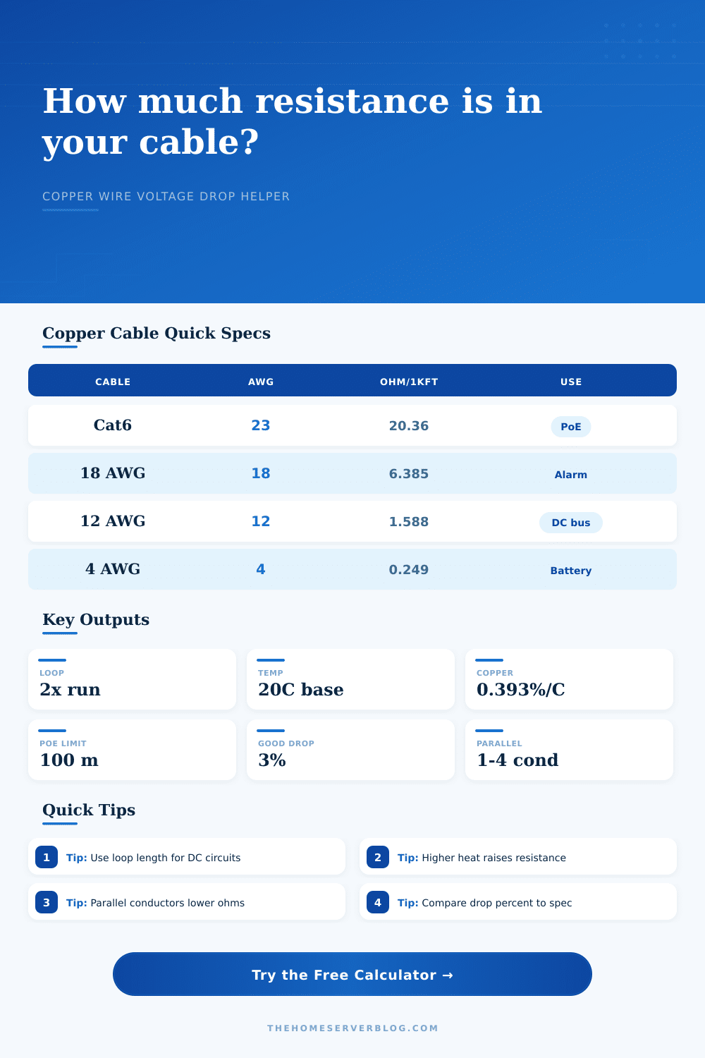
| Conductor | Approx. Area | Ω / 1000 ft at 20°C | Typical Home Lab Use |
|---|---|---|---|
| 23 AWG copper | 0.258 mm² | 20.36 | Cat6 PoE camera or access point channel |
| 22 AWG copper | 0.326 mm² | 16.14 | Cat6A PoE++ cable, patch-panel uplinks |
| 18 AWG copper | 0.823 mm² | 6.385 | Alarm power, relay, sensor, cabinet accessory |
| 16 AWG copper | 1.31 mm² | 4.016 | 24V DC distribution, small fans, LED control |
| 14 AWG copper | 2.08 mm² | 2.525 | Speaker wire, low-voltage rack branch |
| 12 AWG copper | 3.31 mm² | 1.588 | DC bus, short UPS accessory branch |
| 10 AWG copper | 5.26 mm² | 0.999 | UPS output lead, charger cable, high-current shelf |
| 8 AWG copper | 8.37 mm² | 0.628 | Battery shelf, compact inverter, telecom DC link |
| 4 AWG copper | 21.2 mm² | 0.249 | Inverter feed or low-voltage high-current feeder |
| 2 AWG copper | 33.6 mm² | 0.156 | Bench feeder, battery combiner, high-current DC bus |
Values are standard copper conductor approximations. Actual cable assemblies vary with stranding, plating, temperature, connector loss, and manufacturer tolerance.
| Drop Target | Best Fit | What It Means | Planning Note |
|---|---|---|---|
| 2% | Sensitive electronics | Tight regulation at the load | Use larger copper or shorter runs |
| 3% | General branch target | Common design goal for stable voltage | Good default for home lab DC power |
| 5% | Low-voltage accessories | Often acceptable for tolerant loads | Check device input-voltage range |
| 8% | Temporary or noncritical loads | Noticeable sag under current | Review heat and startup behavior |
| 10% | Problem threshold | Usually needs redesign | Shorten, parallel, or upsize the conductor |
| Cable Standard | Typical Copper | Distance Limit | Resistance Concern |
|---|---|---|---|
| Cat5e horizontal | 24 AWG solid | 100 m channel | Higher PoE loss on long runs |
| Cat6 horizontal | 23 AWG solid | 100 m channel | Common balance of speed and PoE drop |
| Cat6A horizontal | 22 to 23 AWG | 100 m channel | Better for hot bundles and PoE++ |
| Zip cord / speaker | 18 to 12 AWG | Load dependent | Resistance affects power and damping |
| Battery cable | 8 to 2 AWG | Short preferred | Loss becomes heat at high current |
| Temperature | Copper Factor | Scenario | Why It Matters |
|---|---|---|---|
| 10°C | 0.961 | Cool basement rack | Resistance is slightly lower than the 20°C table |
| 20°C | 1.000 | Published reference point | Base value used by this calculator |
| 30°C | 1.039 | Warm office wall cavity | Small but measurable added voltage drop |
| 45°C | 1.098 | Crowded cable tray | Bundled PoE runs may need margin |
| 60°C | 1.157 | Hot attic or equipment closet | Review both drop and cable temperature rating |
| Project | Example Load | Resistance Watchpoint | Practical Adjustment |
|---|---|---|---|
| PoE camera at garage | 48V, 0.25A, 180 ft Cat6 | Long channel and patch leads | Use solid copper cable and keep below 100 m |
| Ceiling AP with PoE++ | 48V, 1.2A, 230 ft Cat6A | Higher current raises I²R loss | Prefer 22 AWG Cat6A and avoid tight bundles |
| 24V rack fan rail | 24V, 2A, 35 ft 16 AWG | Small voltage budget | Move supply closer or use 14 AWG if sag appears |
| 12V storage shelf | 12V, 5A, 12 ft 12 AWG | Low voltage magnifies drop percent | Use short leads and check connector resistance |
| UPS battery jumper | 24V, 30A, 6 ft 8 AWG | Copper loss becomes heat quickly | Keep jumpers equal length and mechanically protected |
Patch the camera; you install the switch. But there’s no light from that LED. The port are active and the cable is good, but the electricity couldn’t make the trip. In a PoE or low-current DC network, voltage drop can cause this problem. This isn’t like melting insulation or tripping breakers. It simply deprives your devices of the voltage necessary for them to start up.
Most builders guesses at wire size. They assume that any old standard ethernet cable will do just about anywhere. Guessing costs more time then the copper ever would.
How to Fix Low Voltage in Cables
Once you know how long and where you’re going to be using it, the calc does all the math for you (above). No need to try to do conversions, figure out coefficients, etc. It takes your distance in real world terms and converts it into resistance.
Resistance is friction. Resistance is like friction for electrons. The smaller the diameter of the wire strand, the higher the resistance. The longer the wire, the more higher the resistance. The more resistance, the less voltage get to the end of the line. And some of that resistance are turned into heat.
A piece of copper twisted up into a Cat6 is roughly 23 AWG, and in a standard Cat6 cable it’s around twenty ohms per thousand feet. Sounds small right? Multiply that by two since there are two strands, one to send and one to recieve. Then, multiply that again by however many thousands of feet of actual cable run you have. Then you’ve got yourself something to worry about.
How hot is too hot? It turns out, pretty hot. Resistance increases about four tenths of a percent per degree celsius over twenty degrees. That means if your copper get hot it won’t conduct as well. If you’re running a long cable through a hot attic or a crowded cable tray, then your base line goes up. Your room temperature calculation won’t be accurate enough when temperatures rise next summer. Enter the ambient temperature and the tool will adjust the resistance value to account for it. This little tweak to the inputs avoids a big headache in the field.
The voltage drop limitations is primarily a matter of stability. Two percent is too much for sensitive electronics. The general target is about three percent. Five percent is pushing it but okay if you’re carrying tolerant loads such as motors or lights. Anything more than this and all bets are off. Something rated for 48 volts may well brown out at 44. It may reboot. And then reboot. It happens over and over again. Rebooting also creating heat and stress on the device. The closer the source voltage match the plug voltage, the better it will be for the hardware.
The solution is heavier wire. This works. But costs more. Stiffens things up. A 4 AWG cable is HEAVY. It won’t flex around a corner. It is overkill for a camera. It is perfect for a battery feed. Match the gauge to the amp load. If you’re pulling high amps, use thick wire. Light amps can squeak through thin wires. PoE cams draws modest amps. UPS/inverters draw heavy ones. Treat ’em accordingly.
If you don’t have a thicker single conductor, then use parallel conductors. Bundle up some spare pairs in an existing Cat6 and carry the load together. Doubling the path halves the resistance. This is a neat trick if you’re retrofitting. Make sure the connections are solid at both ends. A loose lug cancel the parallel benefit.
Wire loss is not the same as connector loss. Terminal blocks introduce resistance. Oxidized lugs introduces resistance Patch panels introduces resistance The calculator considers the copper, not the dirt on your contacts. Crimp ‘em hard and clean your connections. Leave a buffer for these real world imperfections. A ten percent design cushion will cover the gap between theory and practice.
Measure the physical path first. Don’t plan the route after you’ve purchased the wire. Walls add length, the ceiling adds length. Straight line distance is a lie. The run may be one hundred feet but the cables probably going to be one-hundred-and-twenty. Tack on that length when you do your calculation. Just enough to flip the decision from risky to safe.
Voltage = Water Pressure. Longer pipe/narrower pipe = less pressure. Enough pressure to turn the wheel. You don’t want infinite pressure. Just enough. The math tells you where that line is. Don’t ignore it. A small failure is a dark camera, and a big failure is rebooting a server rack. Get the wire right the first time. Electricity will stay where you put it.