Symbol Rate Calculator
Plan RF modem symbol rate, occupied bandwidth, and spectral efficiency from payload throughput, modulation order, FEC, roll-off, overhead, and carrier count.
Calculated RF Link Plan
| Modulation | Bits / Symbol | Example FEC | Net Bits / Symbol | Typical Use |
|---|---|---|---|---|
| BPSK | 1 | 1/2 | 0.50 | Low SNR telemetry and robust command links |
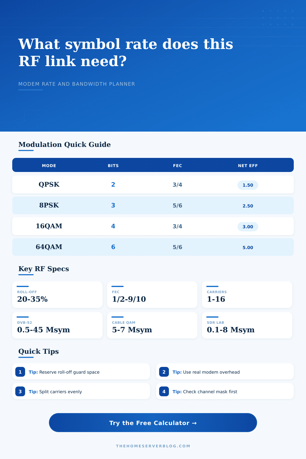
| QPSK | 2 | 3/4 | 1.50 | DVB-S2, VSAT, SDR data, satellite control |
| 8PSK | 3 | 5/6 | 2.50 | Higher-throughput satellite carriers |
| 16QAM / 16APSK | 4 | 3/4 | 3.00 | Microwave PTP, SCPC, controlled RF paths |
| 64QAM | 6 | 5/6 | 5.00 | Cable upstream, OFDM profiles, lab links |
| 256QAM | 8 | 7/8 | 7.00 | Cable downstream and high-SNR short links |
| Roll-Off | Bandwidth Formula | 10 Msym/s Carrier | Where It Appears |
|---|---|---|---|
| 5% | Rs × 1.05 | 10.50 MHz | Tight modern DVB-S2X style carriers |
| 20% | Rs × 1.20 | 12.00 MHz | Common satellite and lab modem planning |
| 25% | Rs × 1.25 | 12.50 MHz | Microwave and many practical RF filters |
| 35% | Rs × 1.35 | 13.50 MHz | Legacy DVB-S and relaxed filter designs |
| Equipment Class | Typical Modulation | Practical Symbol Range | Planning Note |
|---|---|---|---|
| Satellite DVB-S2 modem | QPSK to 32APSK | 0.5 to 45 Msym/s | Roll-off and transponder mask dominate bandwidth |
| Cable QAM channel | 64QAM to 256QAM | 5 to 7 Msym/s | 6 MHz or 8 MHz channel plans set the ceiling |
| DOCSIS upstream group | QPSK to 64QAM | 0.16 to 6.4 Msym/s | Burst overhead and channel bonding matter |
| Microwave PTP radio | QPSK to 1024QAM | 1 to 60 Msym/s | Adaptive modulation changes rate with fade margin |
| SDR transceiver | BPSK to 64QAM | 0.01 to 8 Msym/s | Sample rate and analog filter shape are limits |
| FSK telemetry modem | 2FSK / 4FSK | 0.001 to 1 Msym/s | Deviation and receiver bandwidth set occupancy |
| Project | Payload Target | Likely Profile | Symbol Rate Check |
|---|---|---|---|
| Home DVB lab multiplex | 20 to 30 Mbps | QPSK 3/4 | About 14 to 20 Msym/s before roll-off |
| Remote camera microwave hop | 80 to 150 Mbps | 16QAM 3/4 | About 30 to 55 Msym/s before roll-off |
| Cable QAM emulator | 35 to 45 Mbps | 256QAM 7/8 | Usually near 5 to 6 Msym/s |
| Multi-carrier OFDM test | 200 to 800 Mbps | 64QAM 5/6 | Divide total symbols by active carriers |
| Narrowband field sensor | 0.01 to 0.5 Mbps | BPSK / FSK | Low rate but generous guard bandwidth |
“Why doesn’t my link work like they said? Look on the spectrum analyzer; there’s a bunch of signal bleeding over to other channels. Why isn’t this working?” Most often, it has nothing to do with the cable itself. What it has to do with is math involved in symbol rate.
Symbol rate refer to how many symbols a modem transmits in a second. This sounds similar to how much data you are getting, but it is not the same thing. You can use tricks with modulation density and efficiency to get a lower symbol rate with denser modulation instead of a higher symbol rate with less efficient modulation. Bandwidth and error will then be a whole different story.
How Symbol Rate Works
This is where most amateur RF projects stumble. There’s no magic here; the input parameter are what drive the output of the final link budget. The most obvious factor is modulation order. Two bits per symbol; aka QPSK, is predictable and robust. Sixty-four QAM packs six bit per symbol, which means more data per time slice but requires a much cleaner signal-to-noise ratio. Pushing for higher modulation in a noisy environment will just create more bit errors before your link simply drop out altogether.
Plug in your modulation selection and desired throughput into the calculator and it’ll do the math for you to see exactly how many megasymbols per second it takes to maintain that load.
Forward Error Correction is the safety net that lets you push harder or survive worse conditions. Your safety net is Forward Error Correction. How hard did you wanted it? If you’ve got a clear line of sight microwave hop in good weather, you could of opted for no FEC at all, and really get some more bandwidth. That same FEC enable you to keep going when the rain gets bad on a satellite link. You choose how much error correction, and it’s a tradeoff: do you want more speed or less risk?
A three-quarter code rate means it sends three out of four bits as actualy data. The remaining bit is extra data that receiver can use to repair any corrupt or lost bits without requesting a resend. This means the tool understands what has to expand. It assumes the FEC will take up space to repair errors so your calculated symbol rate takes that into account.
There’s an invisible tax on bandwidth called filter roll-off. In the ideal world of a perfect rectangular filter, there’d be no need for additional space other than the symbol rate itself, but we don’t live in that world. Instead, root-raised-cosine filters is used, which generally have a roll-off factor ranging from five to thirty-five percent. The smaller the number, the more closely-packed the signals (saving spectrum) but the harder they are to filter without interfering with each other. The larger the number, the more breathing room the signal has (making it easier to filter), but more valuable bandwidth is wasted. Enter a 20 percent roll-off and your occupied bandwidth increase by that fraction, a small penalty, but one that ensures non-interference between adjacent channels.
Overhead is the silent killer of throughput. That’s stuff like protocol headers and guard intervals and pilot tones used to synchronize a link. It is all necessary to the operation, but it does not carry any user data. If you don’t account for them your projection will be overly optimistic because they use up time on the wire. And the calculator allows you to put in those percentages so you can remove the idea of perfect efficiency and see how much keeping a connection synchronized really cost.
There’s another wrinkle, however: multi-carrier systems. If you’re combining multiple carriers to increase your throughput, the symbol rate are divided up between those carriers. This alters the required SNR per carrier and makes it more resistant to narrowband interference. The page has a table that sets out common configurations, ranging from wide cable channels down to tight satellite carriers, so you have some sort of baseline for what’s typical in either domain.
In the end, designing an RF link boils down to trade-offs. How much throughput can I get on a given amount of bandwidth? It depends off the equipment and the environment (noise floor). In radio frequency engineering, there’s no such thing as a free lunch. Increasing your data rate has a cost in terms of bandwidth or power or complexity. Understanding this relationship between overhead, FEC, and modulation lets you go from guesswork to engineering. The numbers speak for themselves; provided that you know what questions to ask them first.