Home lab link planner
Insertion Loss Budget Calculator
Estimate cable attenuation, mated connector loss, splices, splitters, passive components, receive power, and remaining margin for fiber and RF/coax links.
▣Presets
⚙Link Inputs
Full Loss Breakdown
⚒Equipment / Spec Comparison Grid
LC Duplex Fiber Path
Common for SFP and SFP+ patching. Count every patch panel and coupler as another mated pair.
Fusion Splice Tray
Low-loss splice point used for permanent fiber extensions, pigtails, and outside-plant transitions.
2-Way Coax Splitter
Typical RF splitter loss before connector and cable losses. Higher split counts consume budget quickly.
LMR-400 Feedline
Useful for ham, LoRa gateway, and lab antennas where coax attenuation must stay predictable.
📊Reference Tables
| Fiber medium | Typical wavelength | Loss allowance | Home lab use |
|---|---|---|---|
| OM3 multimode | 850 nm VCSEL | 3.0 dB per km | Short 10G rack or room runs |
| OM4 multimode | 850 nm VCSEL | 3.0 dB per km | Cleaner margin for 10G and 25G lab trunks |
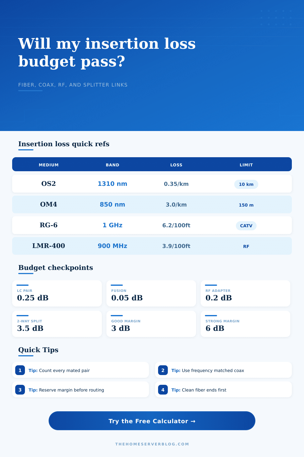
| OS2 singlemode | 1310 nm | 0.35 dB per km | Garage, shed, and building links |
| OS2 singlemode | 1550 nm | 0.22 dB per km | Longer passive optical paths |
| Connector allowance | LC / SC / ST | 0.25 to 0.50 dB per pair | Use the higher value for field terminations |
| Splice allowance | Fusion splice | 0.05 to 0.10 dB each | Include pigtails and repair sleeves |
📡RF and Coax Loss Reference
| Coax or component | Frequency point | Typical insertion loss | Planning note |
|---|---|---|---|
| RG-6 quad shield | 1000 MHz | 6.2 dB per 100 ft | Common CATV, satellite, and camera trunk cable |
| RG-11 | 1000 MHz | 3.6 dB per 100 ft | Lower loss for longer in-home distribution |
| LMR-240 | 900 MHz | 6.9 dB per 100 ft | Short IoT and lab antenna jumpers |
| LMR-400 | 450 MHz | 2.7 dB per 100 ft | VHF/UHF feeds and gateway antennas |
| LMR-400 | 2400 MHz | 6.8 dB per 100 ft | Wi-Fi lab runs should stay short |
| RF adapter pair | Broadband | 0.1 to 0.3 dB each | Budget adapters, surge protectors, and barrels |
🗂Capacity by Configuration
| Configuration | Usual endpoint budget | Preferred spare margin | Practical limit check |
|---|---|---|---|
| 10GBASE-SR OM3/OM4 | About 7.3 dB optical budget | 2 to 3 dB | Connector count matters more than cable length in a home rack |
| 10GBASE-LR OS2 | About 6.2 dB optical budget | 3 dB | Long cable is usually acceptable if panels stay clean |
| GPON style passive drop | About 28 dB class budget | 3 to 6 dB | Splitter loss dominates the calculation |
| CATV home trunk | Designer supplied level window | 3 dB | Splitters and high-frequency coax loss stack fast |
| LoRa or ham feedline | Set by radio and antenna plan | 1 to 3 dB | Long coax can erase transmitter output at the antenna |
🧮Common Project Size Examples
| Project | Medium and distance | Passive parts counted | Expected result | Best adjustment |
|---|---|---|---|---|
| Rack-to-rack 10G | OM4, 25 m | 4 LC pairs, no splices | Usually under 2 dB total | Clean end faces and avoid extra couplers |
| Detached garage SFP+ | OS2, 70 m | 4 LC pairs, 2 splices | Usually under 2 dB total | Use tested pre-terminated cable where possible |
| Satellite TV branch | RG-6, 90 ft | 4 connectors, 2-way splitter | Often near 9 to 10 dB | Move splitter closer or step up to RG-11 |
| LoRa gateway antenna | LMR-400, 65 ft | 2 adapters, surge arrestor | Often around 3 dB | Shorten coax or relocate radio enclosure |
| Wi-Fi lab test cable | LMR-400, 25 ft at 2.4 GHz | 4 adapters | Often around 2 dB | Calibrate the cable before measurements |
ℹPlanning Tips
The link light remains dark. You pull the patch cord from rack and plug it into the switch. Everything looks okay with the port and cable itself. Hardware isn’t always broken. Sometimes there’s simply too much loss along the way. Light degrades over distance and each connection sucks energy out of signal. That’s why if you don’t consider that drain you end up with a slow, or dead. Connection that used to be your high-speed network.
That’s where an insertion loss budget comes into play. It’s not just a line item on a spec sheet; it’s the distinction between a working link and a silent failure. All that stuff is handled by the calculator above. You plug in the cable length, the number of connectors on each end, and the splitters used. It does the math for you so you don’t need to guess if a given run will make it through.
How to Plan Your Connection Loss
How do you know what all these things mean? What goes into them? Well, the length you put in is the attenuation, the base loss in decibels per kilometer of fiber optic cable. Different wavelengths and types has different attenuation rates. So singlemode fiber like OS2 have really low loss and can carries signal extremely far without any real issue. Multimode fiber like OM4 is more lossy, which is why its effective range are shorter for the same data rate. The tool takes your number and translates it to the specific decibel value appropriate to whatever media you chose.
Next are the connectors. Here’s the point at which most people drop the ball with their home lab build. You buy fancy transceivers, but who cares about those crappy patch panels? Each connector add loss when mated up. Cleanliness is also key here. More loss comes from a dirty connector then the connector itself. The calculator assumes there’s some amount of loss per connector pair. Reality is different: cleanliness is king. If you’ve got oil or lint on your end faces, expect your true loss to be higher than what you planned for. Hygiene won’t save you. You can’t calculate your way around it. Clean your connectors before testing the link.
The heavy lifters for passive optical networks are called splitters. They split the light power and they also introduce a large drop in signal strength. An eight-way splitter drops the signal even more. This is known as passive loss and the calculator takes that into account. The splitter loss is fixed regardless of cable length. Better cable won’t lower splitter loss. Only putting splitters closer to the source will do that, or use fewer of them.
The same principle applies for coax and RF links. The longer the run, the greater the loss in coaxial cable. That run may be just fine for 450 MHz but fail at 2.4 GHz because the higher frequency signal fades quicker. The reference tables on the page makes this clear and demonstrate that different cables (RG-6 vs. LMR-400 behaves differently based off the band.
You get back an overall insertion loss and what it compares to what your receiver can pick up. Then you compare that to your received power. If you’re over the minimum limit, congratulations, you have a margin. Your margin is your insurance policy. It’s going to cover you when you bend your cable just slightly too far. When a component starts getting old. When the temperature starts to shift. Ideally you want to have a few decibels of margin. Three decibels is sometimes said to be the bare minimum to ensure a stable link. Six is comfortabley.
But if your calculator tells you you’re negative on margin, that means your link will probably drop some packets or maybe even fail completely. Don’t ignore a negative number here. The path is simply too lossy for the hardware you’ve selected.
“But I can get a higher power transmitter,” you say. “It’ll fix it.” Not always. Sometimes, yes. But often, no. A transceiver is limited to an output range. Once the path loss is beyond that range, no amount of tweaking will help.
The answer is typically passive: reduce the cable run. Use good connectors instead of bad ones. Eliminate needless adapters. Clean the fiber. All these little tweaks accumulate fast. Essentially, you want to minimize the number of times the signal needs to go through a connection point. Less is more. Little things add up. A single connector pair may be just a quarter of a decibel. No big deal. Four pairs? Then you’ve lost a whole decibel. Add in any splitter loss or cable attenuation and you’re halfway through your budget. The calculator reveals those sneaky expenses. It compels you to tally taps, splices, and adapters. Suddenly the link isn’t a wire, it’s a chain of resistance points.
But again that’s all about setting realistic expectations. Before you even yank a cable around, it’s important to understand what this medium can and cannot do. And once you’ve got the cable in the wall, good luck shortening it. You have to live with what you’ve got. If you plan your budget now, then you don’t have to get out your level and tear up drywall because your run failed, and you certainly aren’t heading to the roof to rerun some wire. You did the math ahead of time so that you know what works and what doesn’t. That costs you a few seconds but is worth way more than just plugging something in to see if it lights up. Seeing everything work out in the end is the payoff for doing the math upfront.