TCP Retransmission Timeout Calculator
Estimate TCP RTO from SRTT, RTTVAR, clock granularity, minimum timeout policy, and exponential retransmission backoff.
⚙️Real TCP/RTO Presets
📶RTO Inputs
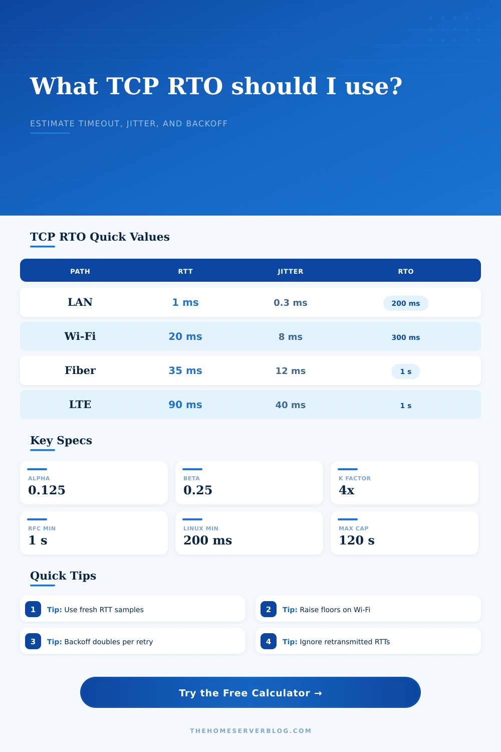
The calculator uses the classic TCP estimator: RTTVAR update with beta 1/4, SRTT update with alpha 1/8, and RTO = SRTT + max(G, 4 x RTTVAR), constrained by the selected floor and profile cap.
Full RTO Breakdown
🖥️Equipment And Network Spec Comparison Grid
📊Reference Tables
| TCP Estimator Item | Common Value | Used For | Home Lab Meaning |
|---|---|---|---|
| Alpha | 1/8 or 0.125 | SRTT smoothing | New RTT samples change the average slowly. |
| Beta | 1/4 or 0.25 | RTTVAR smoothing | Jitter responds faster than the smoothed RTT. |
| K | 4 | Variation multiplier | More jitter means a much wider timeout. |
| G | 1 to 10 ms | Clock granularity | Small timer resolution floor before adding variation. |
| RFC RTO floor | 1000 ms | Minimum timeout | Prevents needless retransmits on ordinary WAN paths. |
| Scenario | Typical RTT | Jitter Band | RTO Behavior |
|---|---|---|---|
| Switch-to-switch LAN | 0.2 to 2 ms | Very low | Often controlled by minimum RTO floor. |
| Home Wi-Fi mesh | 8 to 45 ms | Bursty | Roaming and retries can widen RTTVAR quickly. |
| Fiber WAN | 10 to 60 ms | Low to medium | Stable paths usually remain near the configured floor. |
| LTE backup WAN | 50 to 180 ms | High | Radio scheduling creates larger backoff windows. |
| GEO satellite | 550 to 750 ms | Medium | Base RTT alone can approach or exceed one second. |
| Profile | Default Floor | Default Cap | Best Fit |
|---|---|---|---|
| RFC 6298 standard host | 1000 ms | 60 s | Portable standards-based planning. |
| Linux home server stack | 200 ms | 120 s | NAS, Proxmox, Docker hosts, and local services. |
| Low-latency rack / data center | 200 ms | 30 s | Fast east-west traffic and lab clusters. |
| Home Wi-Fi / roaming clients | 300 ms | 60 s | Laptops, phones, AP roaming, and wireless bridges. |
| High-latency satellite path | 1000 ms | 120 s | Remote monitoring and backup links. |
| Retry Count | Multiplier | Example From 1 s RTO | Operational Note |
|---|---|---|---|
| 0 | 1x | 1 second | Initial timeout before any exponential growth. |
| 1 | 2x | 2 seconds | First retransmission backoff interval. |
| 2 | 4x | 4 seconds | Often visible as a short application pause. |
| 3 | 8x | 8 seconds | Repeated loss can dominate page or file transfer delay. |
| 5 | 32x | 32 seconds | Usually indicates a path, firewall, or congestion problem. |
💡TCP RTO Tips
A TCP timeout causes your application to wait on missing data. Your cursor lags; file transfer freezes; page hangs. You usually detect this lag before you experience the error.
So what happens? How does the OS decide the packet is lost? It sends another one.
How TCP Timeouts Work
By knowing how the operating system handles time, you can solve problems with your network stack and stop blaming your internet provider. TCP keeps track of time for you, but only if you know what those numbers mean. How does it work? It all starts with the Retransmission Timeout, or RTO.
And here’s where the confusion begins: The RTO isn’t a constant value. Since every network has different characteristics, the stack need to estimate its round-trip time and account for some safety margin for jitter. That estimate is based off two smoothed averages. One is the Smoothed RTT; this is your average latency. The other is the RTT Variance, which are how much the latency tends to swing.
Why do we care about the variance? Because if you have a path where latency spikes from thirty milliseconds to eighty milliseconds, that’s bad. You don’t want to expire your timeout before that happens. Doing so causes unnecessary retransmissions, which will only go on to clog the link further.
These is averaged and then weighted with certain weighting factors used in the standard algorithm. The smoother average is updated slowly to reflect that new samples should carries less weight than existing trend. It rapidly updates variance to catch network changes sooner. You’re not just measuring distance; you’re measuring chaos.
To avoid deriving equations yourself, the calculator uses the standard smoothing coefficients. There’s a limitation on the accuracy of your time measurement; it depends on clock granularity. You might have a 10 millisecond tick on your system and therefore couldn’t accurately measure a two-millisecond increase in latency. The algorithm will floor the timeout such that it isn’t less than some multiple of the granularity.
Beyond this, operating systems typically set a policy floor (typically one second) so that healthy links aren’t flooded with retransmissions. So even though your measured RTT approaches zero, the timeout will remain at the floor. That’s because the protocol shouldn’t respond to micro-glitches which don’t affect throughput.
If there’s an issue where packets don’t make it through, the protocol will wait longer and longer between each try. Every time it retries, it waits double as long. So on first try, maybe it waits a second. Then two. Then four. Then eight.
That allows for the possibility that the network could of recovered from congestion. If the stack just hammered away every second, it’d pound the problem link into submission. Check out the reference table to see how fast those waits ramp up. On the fifth retry, you’re waiting thirty-two seconds. That’s an unfortunate compromise to prevent collapse of the whole path.
The real world doesn’t live up to the ideal model. Scheduling cycles in cellular networks causes delay. Wi-Fi has jitter due to interference. Satellite links have hundreds of milliseconds of propagation delay. Tuning approach has to be different for each environment. In a data center with its stable links it can have low timeouts. For a home Wi-Fi mesh where the air is noisy, it should have wide margins.
Plug your observed jitter and latency into the tool and then see what it says theory would recommend. But take that in light of what works in your particular hardware situation. It works well out of the box most of the time. It’s made to be strong.
However tuning can be useful if you want to get better performance, and also for troubleshooting issues. The fact that your RTO keeps hitting the bottom of its range indicates you’re probably having a problem with buffering or packet loss somewhere else. The timeout lets you know there is an issue way before connection fails.
The goal isn’t to make the timeout as small as possible; you want it accurate enough to avoid false alarms while staying short enough to recover from real ones. You want it low enough to respond to real issues but high enough not to raise false alarms. That way the Internet doesn’t grind to a stop.