Fiber Optic Distance Calculator
Estimate one-way and round-trip timing for fiber runs, optics, and active hops in home labs and backbone links.
Full Breakdown
| Fiber Type | Group Index | Delay | Best Use |
|---|---|---|---|
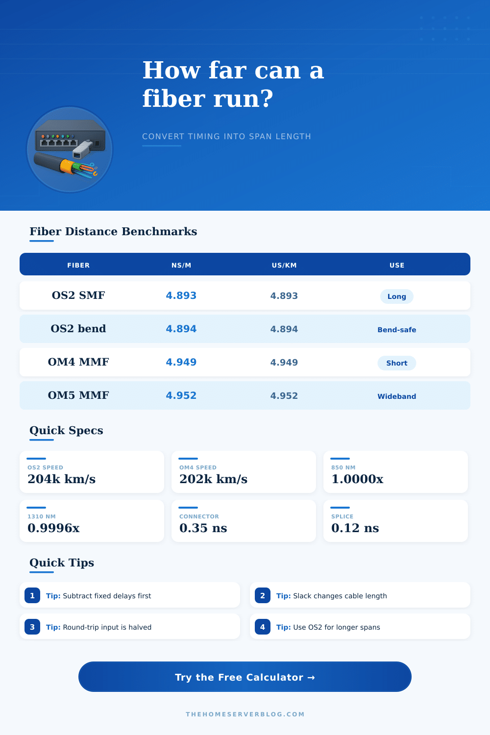
| OS2 single-mode | 1.4672 | 4.893 ns/m | 10 km+ |
| OM3 multimode | 1.4826 | 4.948 ns/m | 300 m |
| OM4 multimode | 1.4827 | 4.949 ns/m | 550 m |
| OM5 wideband | 1.4835 | 4.952 ns/m | 150 m |
| Wavelength | Typical Fiber | Use Case | Note |
|---|---|---|---|
| 850 nm | OM3, OM4, OM5 | Short reach | MMF default |
| 1310 nm | OS2, SMF | General links | Balanced reach |
| 1490 nm | SMF / PON | Access feeder | Often downstream |
| 1550 nm | OS2, SMF | Long reach | Low attenuation |
| Delay Contributor | Model | Added Delay | Comment |
|---|---|---|---|
| Connector pair | Planning allowance | 0.35 ns | Count mated ends |
| Splice point | Planning allowance | 0.12 ns | Usually tiny |
| Transceiver pair | Fixed hardware | 120-260 ns | Depends on optics |
| Switch hop | Fixed hardware | 350-700 ns | Mode matters |
| Scenario | Typical Span | One-Way Target | Notes |
|---|---|---|---|
| Patch lead | Under 20 ft | Under 0.1 us | Mostly optics |
| Floor backbone | 20-200 ft | 0.1-1 us | Keep hops low |
| Campus span | 200 m-2 km | 1-10 us | OS2 preferred |
| PON feeder | 1-20 km | 5-100 us | Splitters add depth |
This calculator keeps optics, glass travel, and active forwarding separate so you can see where distance and delay enter the link.
When you install a fiber optic link between two locations, you must account for the amount of time that it will take for the light to travel from one location to the other. The time that it take for the light to travel along the fiber optic cables is referred to as the latency of that link. Latency occur in fiber optic cables in that the light travels at a specific speed along the glass fiber of that cable.
Light does not travel at the speed of light in a vacuum; the glass of the fiber optic link slows the light signals. Single-mode OS2 fiber optic cables allow for light to travel at a rate of 4.9 nanoseconds per meter. Therefore, each meter of fiber optic cable introduce a delay in the signal along that link.
What Causes Delay in Fiber Optic Links
If one kilometer of single-mode OS2 fiber optic link is used, it will take the light signal nearly 5 microsecond to travel one way along that link. Multimode OM4 fiber optic cables allow for light to travel at a slightly more slow rate than single-mode OS2 fiber optic links, and as such, they is usually used over shorter distances. A variety of different factors will increase the latency of the link, each of which must be accounted for in the installation of the link.
One factor that will increase the latency of the link is the length of the link itself. Any slack that you add to the link will increase the length of the signal path that the light signal must travel. For instance, if 10% slack is added to an 100-meter link, the length of the link will be 110 meters, and the latency will be calculate based off that distance.
In addition to length, latency will also increase if connectors are employ in the link. Each pair of connectors will introduce a small amount of latency into the link. Additionally, any splices that exist along a long link will also introduce latency into the link.
Another factor that will increase latency is the active hardware that exist along the link. For instance, any transceivers will introduce a latency of between 100 and 200 nanoseconds of delay for each pair of transceivers that are employed in the link. Furthermore, switches will also introduce latency into the link; each time a switch make a forwarding decision for the data packet, it introduces hundreds of nanoseconds of latency into the link.
It is important to differentiate between the length of the fiber optic link and the length of the signal path. The route length is the length of the link that is traveled by the signal, but it does not necessarily have to be the distance between the two locations. For links that employ protocols that are sensitive to echo, it is important to calculate the round trip time for the signal.
Round-trip time is the amount of time that it take for the signal to travel to the link and for it to return to its original location. One additional factor that you should of considered is the wavelength of the light signal. Each wavelength will allow the signal to travel at a different group velocity along the link.
For example, passive optical network (PON) splitters may introduce latency into the link even though the number of meters of link is not increase. In order to calculate the total latency of the link, you can take a few steps. First, you can measure the route length of the link.
Second, the fiber optic profile can be selected. Third, the latency that the connectors, the splices along the link, and the transceivers create can be add. Finally, the latency that switches along the link create can be added to the total latency calculation.
By including each of these factors, it will be possible to calculate the total latency that will exist along the link. By understanding the total path along which the light signal will travel along the link, it is possible to determine if the link will function correct before the link is tested.