Point to Point Link Calculator
Estimate receive signal level, free-space path loss, fade margin, Fresnel clearance, and practical bridge throughput for home lab, WISP-style, camera, barn, and campus point-to-point links.
Formula Breakdown
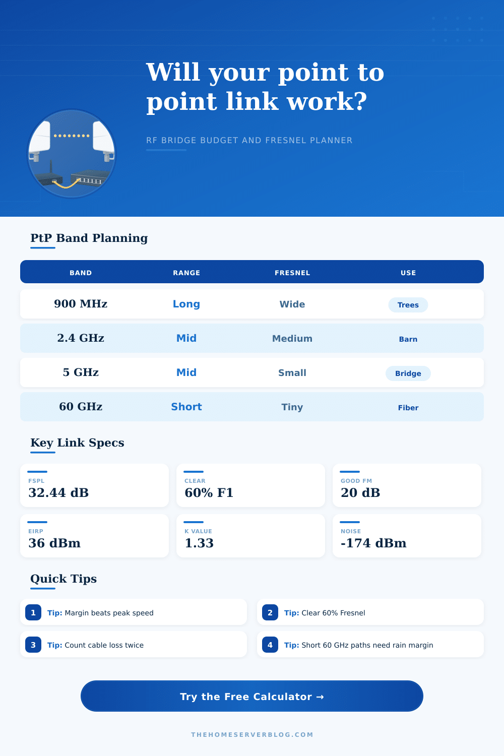
| Bridge profile | Typical channel | Planning strength | Watch item |
|---|---|---|---|
| 900 MHz telemetry bridge | 5 to 10 MHz | Useful around partial foliage and long sensor paths | Large Fresnel radius and modest payload rate |
| 2.4 GHz outdoor Wi-Fi bridge | 20 to 40 MHz | Works well for farms, shops, and detached offices | Interference and antenna alignment still matter |
| 5 GHz AC bridge | 40 to 80 MHz | Strong home lab default for clean line of sight | Tree growth can remove fade margin quickly |
| 6 GHz Wi-Fi 6E bridge | 80 to 160 MHz | High capacity with cleaner channels | Receiver sensitivity rises for wide channels |
| 60 GHz millimeter-wave bridge | 2160 MHz | Fiber-like short hop capacity | Rain, oxygen absorption, and pointing reserve |
| Formula | Expression | Used for | Practical interpretation |
|---|---|---|---|
| Free-space path loss | 32.44 + 20log10(km) + 20log10(MHz) | Core RF path attenuation | Distance and frequency both raise loss logarithmically |
| EIRP | TX dBm - TX loss + antenna dBi | Radiated level from Site A | Check local rules before increasing power or gain |
| Receive level | EIRP - FSPL - path loss + RX gain - RX loss | Signal expected at far radio | Compare against sensitivity and noise-limited threshold |
| Thermal noise floor | -174 + 10log10(Hz) + noise figure | Bandwidth noise estimate | Wider channels need more received signal for same SNR |
| First Fresnel radius | 17.32 x sqrt(d1 x d2 / (GHz x D)) | Mid-path clearance check | Use at least 60% clear for a stable data bridge |
| Net fade margin | Expected behavior | Good use case | Change to consider |
|---|---|---|---|
| Under 6 dB | Likely unstable under weather, alignment drift, or noise | Temporary tests only | Lower channel width or raise antennas |
| 6 to 12 dB | Usable but sensitive to seasonal and interference changes | Noncritical cameras or lab links | Add gain, reduce path loss, or choose cleaner band |
| 12 to 20 dB | Healthy for many home and small-site bridges | NAS replication, office extension, reliable cameras | Monitor noise floor and alignment annually |
| 20 dB or more | Strong planning margin for production-style service | Backhaul, campus, and always-on network segments | Confirm EIRP, lightning, and mounting details |
| Project scenario | Common distance | Primary calculator target | Secondary check |
|---|---|---|---|
| Detached garage bridge | 0.05 to 0.3 mi | Throughput and clean Fresnel line | Do not overpower short links into distortion |
| House to barn office | 0.2 to 1.5 mi | Fade margin over seasonal foliage | Lower channels may beat wider channels |
| Lake cabin backhaul | 1 to 8 mi | FSPL, Fresnel, and multipath reserve | Water paths can reflect and fade sharply |
| 60 GHz driveway hop | 0.02 to 0.5 mi | Rain reserve and high-capacity headroom | Check mounting rigidity and alignment |
| Rooftop campus backhaul | 0.5 to 5 mi | Fade margin and interference-limited SNR | Use narrower beams where noise is high |
This calculator is for planning estimates. Final deployments should verify local EIRP rules, exact terrain profiles, antenna polarization, mounting rigidity, lightning protection, measured noise floor, and manufacturer data sheets.
A point-to-point link calculator can help you to determine if the signal will travel from one location to another. When data are to be moved between two buildings, the radio signal itself is not the primary concern. Instead, the path between those two buildings must be able to carry the signal.
There are a variety of reasons that the path between two buildings might fail to carry the signal, such as if trees grows leaves within that path, if there is a weather event between the two locations, or if a structure is build in between the two buildings. A point-to-point link calculator can provide a decision of whether or not that link will work between the two buildings. One of the variables that the calculator consider is the distance between the two buildings.
How a Point-to-Point Link Calculator Works
This is often the most important of the variables to enter into the calculator. Distance is more important than the wattage of the radio signal that is to be transmitted from one location to another. The loss of signal in free space increase as the distance between the two points increases; if the distance between the two buildings is doubled, the loss of signal increases by approximately six decibels.
Five miles of distance may result in a significant loss of signal, but ten miles of distance will have a loss of signal that dictates the type of equipment that must be used to connect the two buildings. The actual distance between the buildings should be entered into the calculator, not an estimate of the distance between the two buildings based off a map. The frequency that the signal will travel at is another variable.
The frequency will impact the size of the Fresnel zone that is create between the two buildings. The Fresnel zone is a football-shaped area of air that must remain clear of any obstructions. Frequencies like 900 MHz creates a larger Fresnel zone than frequencies like 5 GHz or 6 GHz; the larger Fresnel zone allows for signal loss due to some of the branches of the Fresnel zone entering the buildings.
The downside to using 900 MHz frequencies, however, is that they dont carry as much data as the higher frequencies. The higher the frequency used, the smaller the Fresnel zone; this allows for more clearance between the buildings, but it also means the signal will experience more loss due to rain or oxygen molecule absorbing the signal. The calculator allows the user to select different frequency bands to see how the requirement for the Fresnel zone will change.
The height of the antenna that will be used is another variable. The height of the antenna impacts the geometry of the signal path, as well as how the signal interacts with the Earth. The higher the antenna is raised, the less of the Earth bulge that the signal will have to travel over.
If the link between the two buildings is very long, the bulge of the Earth is a distance that must be considered. The calculator considers the Earth radius, or the K-factor, which allow the link budget calculator to determine in what type of terrain the signal will travel. Fade margin is a number that indicates how many decibels of signal loss the link can experience before it becomes unable to maintain the link between the two buildings.
If there is a fade margin of six decibels, that may be appropriate for a link that transmits a camera signal between two locations. For a link that is considered a production link, however, the fade margin should be stronger. Production links may require a fade margin of fifteen or twenty decibels to remain stable during the summer when the foliage between the buildings may cover the link, or during the winter when the link may experience icing.
The calculator shows the fade margin to determine whether the antennas that are to be used will provide a fade margin that is adequate for the link between the two buildings. The Fresnel zone has its own measurement that is calculated in the link budget calculator. The calculator can determine the Fresnel zone by subtracting the size of the Fresnel zone and a growth reserve from the distance between the two buildings in a straight line.
The result of this calculation will be the amount of clear space between the two buildings. If the result of the calculation in the link budget calculator is a negative number, it does not mean that the link cannot work; it means, however, that some of the signal will have to rely upon diffraction properties of the lower frequencies to reach the second building. Many link budget calculators allow the user to set a requirement for the link to ensure that the link will remain open.
One such rule is the 60 percent clearance rule. The 60 percent clearance rule establishes that the link will work better if there is a 60 percent Fresnel zone that is clear of any obstructions. This rule is established as a balance between the need for the link to remain open and the cost of building the antennas to higher heights to allow that percentage of the Fresnel zone to remain open.
Throughput calculations are performed with the link budget calculator, as well. The throughput calculations are dependent upon the other variable. The link budget calculator calculates the throughput of the link based upon the signal strength that is received, the noise that is measured in the link, and the relationship between those two variables.
The larger the fade margin, the more data that can be sent between the two locations. The link will allow the signal to use wider channels and higher order of modulation if the fade margin is strong. If the fade margin is thin, the link will use narrower channels and lower order modulation to ensure that the link remains open; the throughput will change if the antenna height is changed or if an obstruction to the signal between the buildings is moved.
Another component of the link budget calculator is the inclusion of reference tables. One table provides information about the different type of bridge profiles and the distances at which the links will function best. Another table includes information about the effect of channel widening on the noise in the link.
A third table includes information about the relationship between fade margin and link behavior; this table can allow the link budget calculator to determine whether more antenna gain is required for the link or whether the distance between the two buildings should be shortened. In addition to the link budget calculator, there are a variety of other variables related to the link that will impact the link between the two buildings. The rigidity on which the antennas will be mounted is one of those variable.
If the mount that is used for the antennas is not rigid, it is possible for a shift of even half a degree in the alignment of the antennas to cause the signal to fall off the receiving antenna at the second location. Another variable is the noise floors in the environment in which the link will exist. If there are other access points in the vicinity of the buildings, or if the buildings has metal roofs, it is possible that the link will be affected by this additional noise or signal reflection.
Another variable is that each antenna installation will require lightning protection and grounding system to protect the equipment. These factors, however, are not directly considered in the link budget calculation. The link budget calculator can provide good guidelines to installation of the antennas, but the installation should also perform an actual measurement of the noise floor in the link with a spectrum analyzer.
One of the most common mistake in the use of a link budget calculator is using the first results of the calculations as the final result. The antenna height should be changed, the location of an obstruction to the signal should be changed, or the channel width can be changed to see how the link budget calculator’s results change. These adjustments can be made within the link budget calculator.
When the results of the link budget calculator indicate that a link will work with the antennas that are to be used, and that the link will not experience any issues during its daily use, then the link will work as intended.