PoE Power Loss Calculator
Estimate voltage drop, cable watts lost, delivered power, and remaining switch budget for PoE access points, cameras, phones, and home lab devices.
Full Breakdown
| Standard | PSE Output | Typical Powered Pairs | Practical Home Lab Uses |
|---|---|---|---|
| IEEE 802.3af Type 1 | 15.4 W at source, about 12.95 W available | 2-pair | VoIP phones, small cameras, basic access points |
| IEEE 802.3at Type 2 | 30 W at source, about 25.5 W available | 2-pair | Wi-Fi 6 APs, IR cameras, small touch panels |
| IEEE 802.3bt Type 3 | 60 W at source, about 51 W available | 4-pair | High-power APs, thin clients, compact PoE switches |
| IEEE 802.3bt Type 4 | 90 W at source, about 71 W available | 4-pair | PTZ cameras, displays, docks, all-in-one terminals |
| Passive 24 V or 48 V | Injector dependent, no automatic class negotiation | Often 2-pair or vendor-specific | Older wireless bridges, lab-only devices, specialty gear |
| Cable Type | Approx. Conductor Resistance | PoE Suitability | Planning Note |
|---|---|---|---|
| Cat5e solid copper, 24 AWG | 25.7 ohms per 1000 ft | Good for standard PoE | Common home cable; watch loss on high-watt long runs. |
| Cat6 solid copper, 23 AWG | 20.4 ohms per 1000 ft | Better for PoE+ | Lower drop than 24 AWG and a safe default for new pulls. |
| Cat6A solid copper, 23 AWG | 20.0 ohms per 1000 ft | Best for bt PoE | Useful when heat, bundles, and 10 GbE margin matter. |
| Slim patch cable, 28 AWG | 64.9 ohms per 1000 ft | Short low-power links only | Keep these to rack jumpers, not long camera or AP runs. |
| CCA cable estimate, 24 AWG | 42.0 ohms per 1000 ft | Not recommended for PoE | Higher resistance raises voltage drop and cable heating. |
| Project | Device Load | Common Cable Run | Suggested Starting Point |
|---|---|---|---|
| Single ceiling AP | 10 to 18 W | 50 to 150 ft | 802.3at with Cat6 copper leaves good voltage margin. |
| Four camera NVR closet | 6 to 12 W each | 80 to 220 ft | Add all PSE watts, then keep at least 10% reserve. |
| PTZ driveway camera | 22 to 45 W | 150 to 300 ft | Use Cat6A and bt PoE when motors or heaters are active. |
| PoE mini switch uplink | 25 to 60 W | 40 to 180 ft | Calculate powered switch draw plus downstream device draw. |
| Outdoor wireless bridge | 5 to 18 W | 80 to 250 ft | Passive gear needs extra voltage-drop attention. |
| Planning Item | Why It Matters | Rule of Thumb | Calculator Impact |
|---|---|---|---|
| One-way length | Cable loss rises with distance. | Keep total channel at or below 328 ft / 100 m. | Longer runs increase resistance and watt loss. |
| Device watts | Higher load means higher current. | Use real maximum draw, not idle draw. | Current squared drives heat loss in the cable. |
| Cable gauge | Thicker copper has lower resistance. | Prefer solid copper 23 AWG for long high-power links. | Lower ohms improves voltage at the powered device. |
| Powered pairs | More conductors share the current. | bt four-pair PoE usually wastes less cable power. | Four-pair mode halves the effective loop estimate. |
| Reserve budget | Switch budgets are shared across ports. | Leave 10% to 20% for startup, cold weather, and future APs. | Reserve subtracts from usable power budget. |
When access points and network cameras stop working because of a storm or a heavy load, it’s not usually a software bug, it’s the laws of physics, specificly, voltage drop. Every piece of copper wire resist electricity. That resistance generates heat. So what starts as full-power from the switch will be diminished by the time it hit the end device.
There’s a power loss calculator for PoE that show the reality of how much power dissipates along your cable before reaching your gear. But the calculator does all that math for you. Simply choose your PoE standard, type of cable, the wattage of the device, and length of the cable run. Then it tell you how much power actualy gets delivered to the device. It takes into account the amount of power lost in the wall due to resistance.
Why Devices Lose Power in Network Cables
That’s what makes a network reliable, or not-so-reliable and in need of constant repair. Lots of folks think a thirty-watt port sends a full thirty watts to the device. Nope. Some of that power goes into powering the cable. The more power you need, the longer the run, the more power are lost.
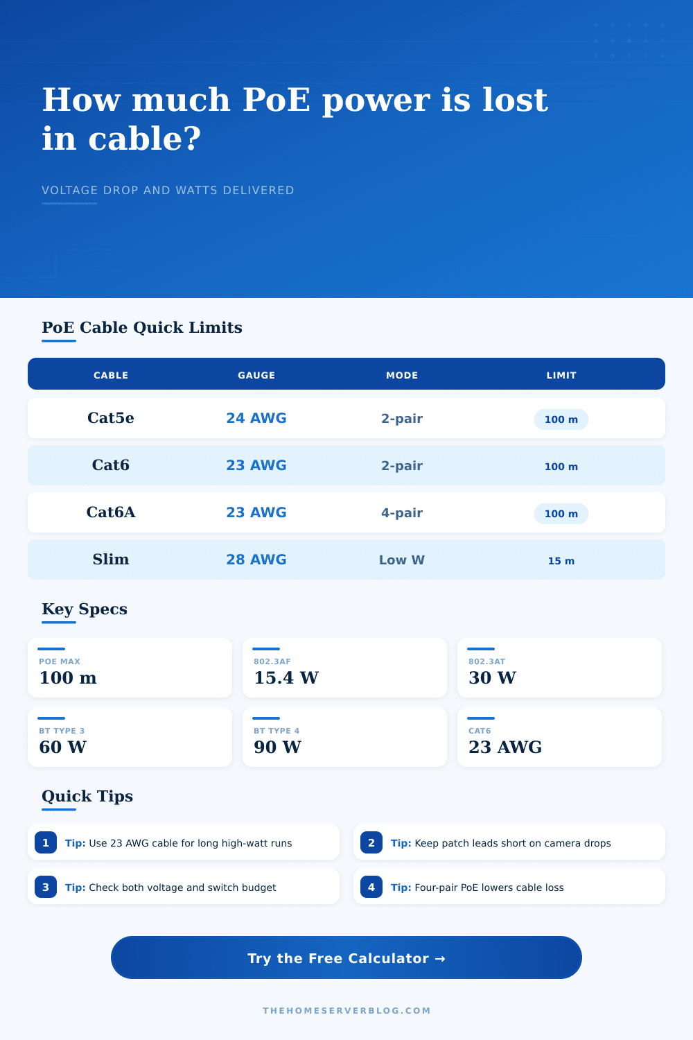
The length also make a big difference. You can get away with running lower-powered devices (like VoIP phones) on cat5e cables over short distances. But if you’re trying to run higher wattage devices (like security cameras or WiFi 6 access points), it don’t work well at longer distances. Cat5e has thin copper strands, which increase the resistance. If you upgrade to thicker 23 AWG wires (Cat6 or Cat6A), then that reduce the resistance. A thicker cable sends more voltage to its end point. And that little tweak will increases your network’s stability. Less friction means electricity flow better.
There are other problems with passive PoE. With cheap injectors, some older gear simply sends out whatever voltage it has to work. That means whatever voltage makes it through the cable is what the device get. Sometimes the voltage drop below what the device can use because of a thin or long cable. This causes all sorts of problems for the device: freezes, resets, malfunctions.
The calculator let you find those problems ahead of time. Enter in your wattage and distance and you’ll see how much voltage will reach the device. If that’s low, then you know you’re on shaky ground.
Power budgets matter when it comes to switches too. Just because a switch has ten 30 watt ports doesn’t mean it supply three hundred watts total. Often, combined power output is less than total of the ports due to the power budget. If each of the ports pulls maximum power, then the switch will throttles back power or even shut down completely. The calculator includes a reserve percent for this limitation. This ensures that you don’t max out the switch and still leave some wiggle room for added power requirements such as cold weather or future expansion.
You should of considered this. These are more efficient four-pair PoE standards. Rather than only using two of the eight available wires in the cable to power a device, with four-pair PoE, they use them all. That way, current is split out among more wires, decreasing heat and voltage drop. It’s typically best practice for longer cable runs if both the cable and your devices supports it. When you choose this standard, calculator automatically accounts for that in its results.
When planning a network, pay attention to the cabling. The cable is the backbone and the weakest link when neglected. Knowing about voltage drop eliminate unexplained device failure. There is no more guesswork, only facts. Instead of wondering why something didn’t work, you know why. Knowing is worth the time needed to run the numbers.