Optical link budget calculator
Fiber Connector Loss Calculator
Estimate connector insertion loss, cable attenuation, splice loss, adapter penalties, cleaning allowance, and remaining transceiver budget for home lab fiber links.
▣ Fiber presets
⚙ Fiber link inputs
Full loss budget breakdown
🖧 Equipment and spec comparison grid
LC UPC Patch Pair
Compact duplex connector common on SFP, SFP plus, SFP28, and many home lab fiber patch panels.
SC APC Drop Pair
Angled green connector often used for provider handoff, PON ONT drops, and low-reflection singlemode links.
MPO Elite Trunk
Multi-fiber connector used by 40G SR4, 100G SR4, parallel optics, breakout cassettes, and dense lab trunks.
Inspection Probe
Used with one-click cleaners and launch leads before final power meter or OTDR acceptance testing.
▦ Connector and equipment comparison
| Connector or tool | Typical loss | Return loss cue | Where it fits | Home lab watch point |
|---|---|---|---|---|
| LC UPC ceramic ferrule | 0.20 to 0.30 dB per mated pair | Good for Ethernet optics | Switch uplinks, SFP cages, compact patch panels | Small endface is easy to contaminate during frequent recabling |
| SC UPC panel coupler | 0.25 to 0.35 dB per mated pair | Common blue singlemode connector | Wall boxes, media panels, ISP demarc extensions | Large connector is sturdy but can hide poor polish or old dust |
| SC APC angled connector | 0.25 to 0.35 dB per mated pair | Lower reflection than UPC | PON ONTs, RF over fiber, provider drops | Never mate green APC to blue UPC adapters or optics |
| MPO elite cassette trunk | 0.35 to 0.50 dB per mated pair | Depends on gender and polish | 40G SR4, 100G SR4, breakout cassettes | Pinning, polarity, and cassette count can exceed the budget quickly |
| Fusion splicer | 0.03 to 0.10 dB per splice | Low reflection when protected | Permanent repairs, pigtail splicing, tray work | Bad cleaves and stressed sleeves create intermittent loss |
| Power meter and light source | Measures end-to-end dB loss | Reference quality matters | Acceptance testing after patching or construction | Set a fresh reference with matching launch and receive cords |
📋 Connector loss allowance table
| Connection item | Typical planning value | Conservative value | Use this when |
|---|---|---|---|
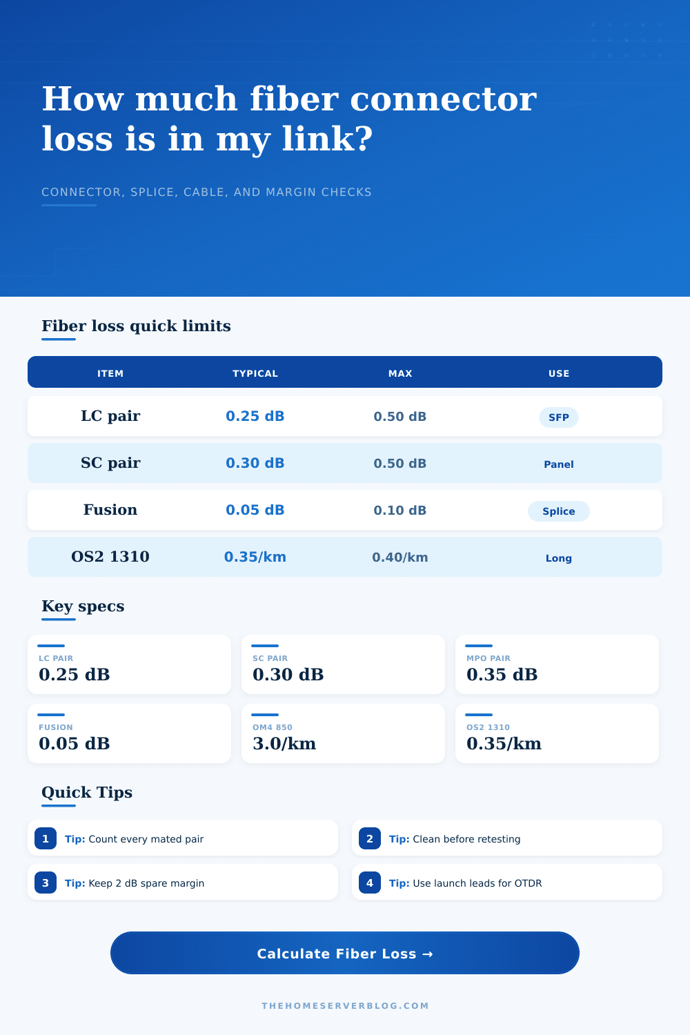
| Factory LC UPC mated pair | 0.20 to 0.25 dB | 0.50 dB | SFP to patch panel, patch panel to equipment, short rack links |
| Factory SC UPC mated pair | 0.25 to 0.30 dB | 0.50 dB | Media panel handoffs, campus wall boxes, older singlemode panels |
| SC APC mated pair | 0.25 to 0.30 dB | 0.50 dB | PON, RF video overlay, or provider circuits sensitive to reflection |
| Field-terminated LC | 0.40 to 0.75 dB | 1.00 dB | Quick field repairs or no-splice connectors in a remodel path |
| MPO or MTP trunk pair | 0.35 to 0.70 dB | 0.75 dB | Parallel fiber links, cassettes, and high-density switch rows |
| Temporary adapter barrel | 0.15 to 0.25 dB | 0.35 dB | Emergency extension, lab bench testing, or mixed jumper lengths |
📏 Fiber attenuation reference
| Fiber type | Wavelength | Planning attenuation | Common application |
|---|---|---|---|
| OM3 multimode | 850 nm | 3.5 dB/km | 10G SR links up to about 300 m with the right optics |
| OM4 multimode | 850 nm | 3.0 dB/km | Dense home lab racks, 25G SR, 40G SR4, short trunks |
| OM5 multimode | 850 nm | 3.0 dB/km | Wideband multimode and future-ready short reach cabling |
| OS2 singlemode | 1310 nm | 0.35 dB/km | 10G LR, 25G LR, building links, long garage or shop runs |
| OS2 singlemode | 1550 nm | 0.22 dB/km | Longer spans where optic compatibility and bend radius are known |
| PON singlemode | 1490 nm | 0.28 dB/km | Provider ONT drops and passive optical network checks |
🔌 Optic budget table
| Optic class | Typical reach | Planning budget | Practical note |
|---|---|---|---|
| 1000BASE-LX | 10 km on OS2 | 8.0 dB | Often forgiving for home runs, but receiver overload can matter on very short links |
| 10GBASE-SR | 300 m on OM3, 400 m on OM4 | 6.3 dB | Connector loss matters more than cable attenuation in racks and closets |
| 10GBASE-LR | 10 km on OS2 | 6.2 dB | Good for detached garage, workshop, and outdoor-rated conduit routes |
| 25GBASE-SR | 70 m on OM3, 100 m on OM4 | 4.0 dB | Tighter budget, so cassettes and dirty patch panels deserve inspection |
| 25GBASE-LR | 10 km on OS2 | 6.3 dB | Singlemode lets cable length disappear for many residential-property spans |
| 40GBASE-SR4 | 100 m to 150 m multimode | 3.5 dB | MPO trunk and cassette loss should be counted per mated array path |
| GPON class B plus | Access drop with splitter | 28.0 dB | Includes large passive splitter loss, so small connector errors still add up |
📝 Common home fiber project sizes
| Project | Typical path | Main loss driver | Budget habit |
|---|---|---|---|
| Rack switch to NAS | 3 to 20 m OM4 duplex | Four LC mated pairs | Keep total loss under 2 dB after margin |
| Office to utility closet | 25 to 75 m OM3 or OM4 | Patch panels and wall plates | Use factory jumpers and inspect before blaming the optic |
| House to detached garage | 50 to 200 m OS2 in conduit | Connector count, not fiber length | Prefer singlemode if conduit access is hard later |
| 40G lab breakout | MPO trunk with LC cassette | MPO pair plus cassette internals | Reserve extra dB because SR4 budgets are tighter |
| Provider handoff extension | SC APC OS2 jumper and coupler | APC cleanliness and reflection | Do not mix APC and UPC polish styles |
| PON ONT relocation | OS2 drop with passive splitter path | Splitter and demarc couplers | Confirm provider optical range before moving equipment |
💡 Fiber calculation tips
Connectors kill most home lab fiber runs. I have pulled perfect singlemode fiber through my 100m long garage and had no luck getting it to work. Why? There were dust particle on the small ceramic ferrule at one end. Light behaves different than you and me. One particle of lint or one microscopic scratch will scatter photons and prevent them from reaching your receiver. On a power meter that’s high loss. Looks like bad hardware. But mostly it’s just dirt on the connector ends.
And there’s the rub: Understanding the link budget ends the guesswork. How much power does your transceiver start out with? And how much has been lost by the time it gets through? Define the path and the calculator above will run the numbers for you.
How to Fix Your Fiber Link Issues
It runs from end to end. It includes length of the fiber, the type, and all the points along the way where it touches a connector. Most folks greatly underestimate the number of actual mating pair they have. Patch cable connects to a switch and a panel? Two connections. Two ends coming together in an adapter. So you count ’em as pairs because that’s where the loss occurs. Double your connectors if you have a patch panel in between. That’s what folks gets wrong. They think in terms of cables instead of interfaces.
Cable attenuation vs. Connector loss occurs. Connector loss Why does this tool split them apart? Because glass is very good at transporting light over short distances. For those short runs, the fiber itself is practically irrelevant. It’s all about what happens at the edges: every time you move light from one cable to another, it gets killed by misalignment and reflection. This is especially true for singlemode because the core is tiny. Multimode is more tolerant, so you see multimode used for shorter hops (like offices). Even then, too much patching will ruin signal.
The calculator includes an allowance for imperfection because nobody ever gets everything right in the field. New patches may be clean as a whistle, but six months of hot-swapping SFP modules messes with that. Oil from our fingertips accumulates. Dust also collects. The allowance ensures your estimate isn’t theoretical but realistically achievable.
Connectors, Connectors are interfaces where loss happens when light exits one cable and enters another through mating pairs. That means reflection back into the other piece of glass, so the calculator shows some loss. A splice joins two pieces of glass together permanently. When done right, they is almost completely invisible to the light unless you are really looking. Since there’s no air gap and nothing reflecting, the calculator applies a lower loss figure for splices than for connectors.
Good design usually includes minimizing connectors, since you’re usually trying to avoid splicing in the first place. Fewer moving parts mean fewer places to fail. Mechanical splices also work, but they cause more loss than fusion. Toggle that option if you’re repairing old runs instead of building new ones, and tool will help you do that too.
But the other metric is budget. How much will it take? Each optic has its limit and can takes only so much loss before it drops out of sight, below the noise floor. That’s what the calculator measures: Your total loss versus the limit. You’re down to one decibel? You’ve got wiggle room, enough to age, change temperatures, use a slightly poorer-than-new connector, and still be fine. You’re at zero? Flap-flap-flap. A single speck of dust is all it takes, and the link is gone. Better to go more rather then less on this margin-chase game of intermittent error.
And don’t skip over the engineering margin setting. This is a buffer in percentage to account for unknowns. Panels will be crowded. Connectors will be reused. Cables will be bent. Twenty percent or even ten percent can make up for the wear and tear after install. It’s insurance against reality.
The page has a reference table showing some standard values by common connector type. These are based off industry standards, not guesswork. Use these as your starting point. Look at the breakdown when you put your numbers into it. Are you seeing connector loss dominate? Make the path simpler: get rid of a patch panel or go direct with a patch cable. Is it cable attenuation? You’re just too far away for that class of optic. Go to a longer reach transceiver or switch to singlemode. It’s typically one or the other.
Fibre is simple. Light goes in, light comes out. If it doesn’t, something’s blocking the way. Half of these problems get solved with cleaning. It’s a penny for a single-click cleaner; wasting an hour testing with a dirty reference cord is wasted hours. Look at the endface before you plug it in. It’s a little ritual that pays off in steadiness. Actually, you should of used more cleaners. Modern setup might feel luxurios but dirt dissapears slowly.