RF planning calculator
Antenna Length Calculator
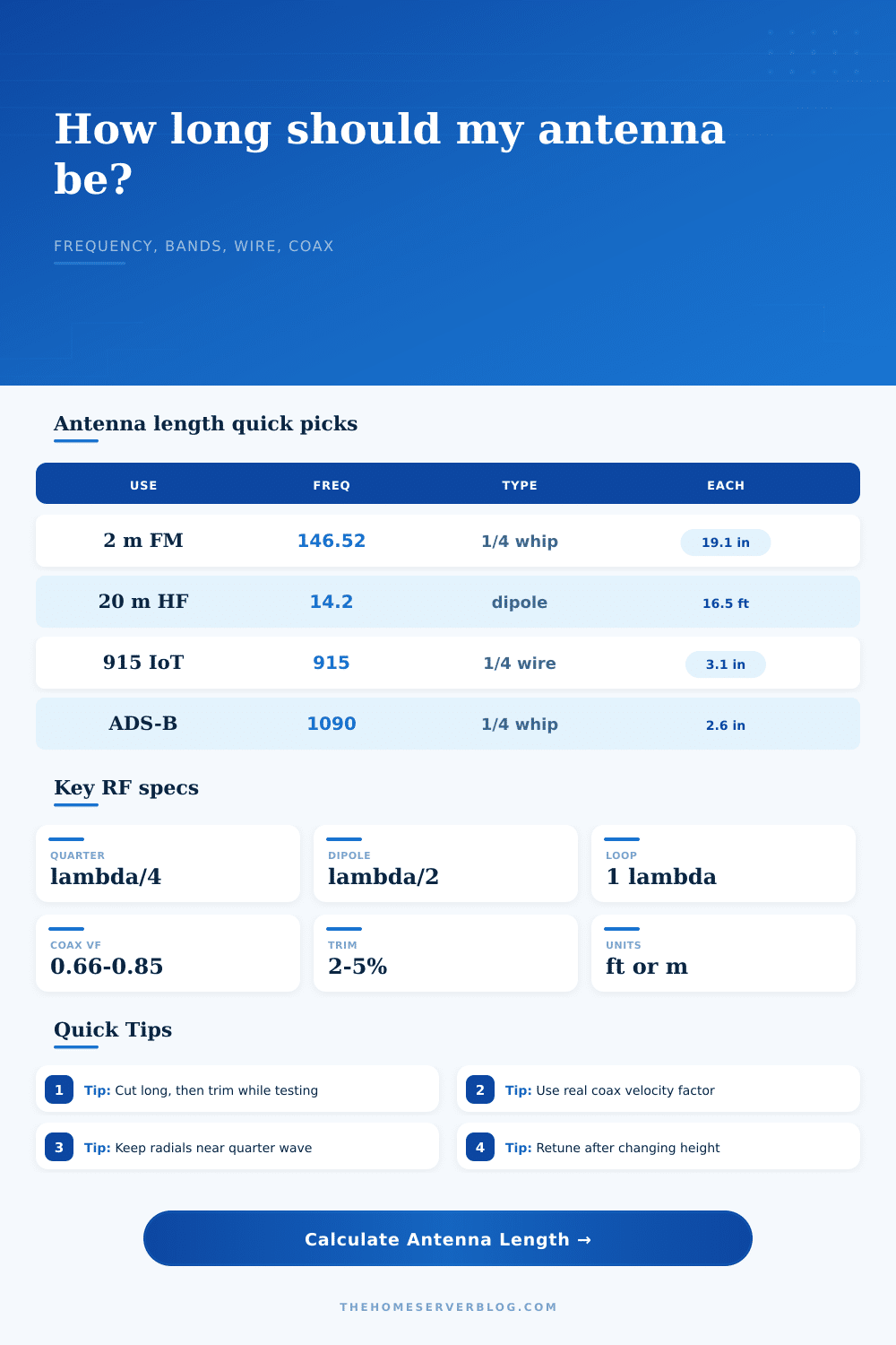
Size quarter-wave whips, half-wave dipoles, full-wave loops, 5/8 verticals, and coax phase sections from frequency, velocity factor, element count, and trim reserve.
▣ Real band and lab presets
⚙ Antenna inputs
Calculation breakdown
▦ Equipment and feed-line comparison grid
RG-58 Patch Coax
Useful for short HF/VHF patch leads. Higher UHF loss makes accurate length and short runs more important.
LMR-400 Backbone
Common home station upgrade for VHF/UHF antennas, SDR masts, and longer roof-to-rack runs.
300 Ohm Twin-Lead
Works well with wire antennas and tuner-fed home lab receive antennas when routed away from metal.
PCB / IoT Trace
Short embedded traces need board dielectric data, ground clearance, and final VNA verification.
☰ Common frequency and antenna lengths
| Service or band | Center frequency | Quarter-wave vertical | Half-wave dipole total | Typical lab use |
|---|---|---|---|---|
| 40 m amateur HF | 7.150 MHz | 32.7 ft / 9.97 m | 65.5 ft / 19.96 m | NVIS, field wire, backup comms testing |
| 20 m amateur HF | 14.200 MHz | 16.5 ft / 5.03 m | 33.0 ft / 10.06 m | Portable dipole and digital station tests |
| CB channel 19 | 27.185 MHz | 8.61 ft / 2.62 m | 17.2 ft / 5.25 m | Receive checks and garage roof whips |
| 2 m calling frequency | 146.520 MHz | 19.2 in / 48.9 cm | 38.5 in / 97.8 cm | FM voice, APRS, scanner receive |
| NOAA Weather Radio | 162.550 MHz | 17.3 in / 43.9 cm | 34.5 in / 87.7 cm | Weather receiver and SDR monitoring |
| 70 cm amateur UHF | 446.000 MHz | 6.31 in / 16.0 cm | 12.6 in / 32.0 cm | Repeater, hotspot, and handheld testing |
| GMRS repeater input/output | 462.600 MHz | 6.08 in / 15.4 cm | 12.2 in / 30.9 cm | Base antenna and family radio testing |
| LoRa / ISM North America | 915.000 MHz | 3.07 in / 7.8 cm | 6.14 in / 15.6 cm | IoT sensors, mesh nodes, telemetry links |
| ADS-B aircraft receive | 1090.000 MHz | 2.58 in / 6.6 cm | 5.15 in / 13.1 cm | Flight tracking SDR receivers |
| Wi-Fi channel 6 | 2437.000 MHz | 1.15 in / 2.9 cm | 2.30 in / 5.8 cm | Bench antennas and RF enclosure tests |
▧ Configuration reference
| Antenna type | Calculator fraction | Element count | Feed notes | Best use |
|---|---|---|---|---|
| Quarter-wave vertical | lambda/4 per element | 1 radiator plus radials | Needs counterpoise or ground plane | VHF, UHF, scanner, IoT nodes |
| Half-wave dipole | lambda/4 per leg | 2 equal legs | 50 to 75 ohm feed near center | HF wire antennas and attic builds |
| End-fed half-wave | lambda/2 single element | 1 long radiator | Requires matching transformer | Portable HF and space-limited runs |
| 5/8-wave vertical | 5 lambda/8 radiator | 1 radiator plus matching | Usually needs loading or matching network | VHF base and mobile-style antennas |
| Full-wave loop | lambda perimeter | Loop perimeter | Impedance varies by shape and height | HF loops, receive loops, quiet installs |
| Radial set | lambda/4 per radial | 4 to 32 radials | More radials usually stabilizes tuning | Ground planes and vertical base antennas |
▨ Velocity factor and cable standards
| Material or cable | Nominal VF | Impedance or type | Length impact | Practical note |
|---|---|---|---|---|
| Bare copper wire | 0.98 | Radiating conductor | 2% shorter than free space | Good first model for open wire dipoles |
| PVC insulated hookup wire | 0.95 | Radiating conductor | 5% shorter than free space | Insulation and nearby surfaces shift resonance |
| Aluminum tubing | 0.99 | Radiating conductor | Near free-space length | Element diameter changes bandwidth and end effect |
| RG-58 / RG-213 | 0.66 | 50 ohm coax | 34% shorter phase sections | Common solid PE dielectric coax value |
| LMR-240 / LMR-400 | 0.84 to 0.85 | 50 ohm coax | 15% to 16% shorter phase sections | Check the datasheet for exact cable family |
| RG-6 TV coax | 0.83 | 75 ohm coax | 17% shorter phase sections | Useful for receive-only SDR experiments |
| 450 ohm window line | 0.91 | Balanced line | 9% shorter phase sections | Keep spacing from metal and wet surfaces |
▩ Project size examples
| Project | Frequency | Recommended starting cut | Secondary length | Verification tool |
|---|---|---|---|---|
| Garage 2 m ground plane | 146.52 MHz | 19.6 in vertical | 4 radials near 19.6 in | VNA or SWR meter |
| SDR ADS-B collinear test | 1090 MHz | 2.7 in quarter sections | Short low-loss coax run | Aircraft message rate |
| 40 m attic dipole | 7.15 MHz | 34.7 ft per leg with reserve | 69.4 ft total wire | Antenna analyzer |
| LoRa sensor enclosure | 915 MHz | 3.2 in quarter-wave | PCB ground clearance check | RSSI and packet loss |
| Wi-Fi enclosure probe | 2437 MHz | 1.2 in quarter-wave | 2.4 in half-wave reference | Spectrum or RSSI scan |
ℹ Build notes
Part carpentry, part chemistry: Making a radio antenna involve cutting the right length of wire or other antenna element. And then the tricky thing is, what’s “right?” Too long, and you get noise in the signal; too short, and you won’t have any range at all.
There are calculators online to help do some of the basic math for you, so you know something close instead of having to guess wildly before you even begin. This one take into account how radio waves travel slower through coax and other type of wire, so your actual antenna won’t be quite as long as the numbers say it should of been.
How to Cut the Right Antenna Length
This is where most hobbyists’ efforts comes to an end. The basic idea is that wavelength is involved. Waves move across space at some finite rate, radio waves and light for example. There is a certain number of them per unit time that moves past any given point (frequency). The wavelength and frequency is related.
Choose a common configuration such as a quarter-wave vertical or a half wave dipole antenna from the list, and you pick that wavelength. Then apply the velocity factor for the material chosen. Bare copper wire travels efficienty, and gets pretty darn near the theoretical length. Thicker building wire or wire insulated with PVC will slow the signal down further, reducing the physical cut needed. That’s what the material choice do.
Why do you care? Because while insulation is not conductive, it does change the electrical path based off the material. Finally, there is the end effect. Theory doesn’t really address this and it’s where things get tricky. Your antenna is not just a piece of wire with an end; the electricity don’t abruptly cease at the end of metal tip. It actualy spreads out into the surrounding air to some extent.
This creates a capacitive load which cause the antenna to act electrically like it has more wire in it than it do. You therefore have to cut the actual wire shorter then what was computed for its electrical length. This is also referred to as a correction factor which the calculator use as a percentage. It’s little, but it makes a world of difference when it comes to resonant behavior. If it wasn’t for it, you might cut your antenna to spec perfectly only to find your SWR meter still reads high.
There is one other wrinkle: feed lines. Velocity factors varies by coaxial cable, and are frequently much below that of either wire or air. For example, RG-58 cable has a velocity factor of roughly sixty-six percent. This means that a quarter-wave matching section of RG-58 will be quite a bit shorter than an open-wire quarter-wave section. The table on the page show this clearly and illustrates how variation in cable alters the required physical length of a matching section. If you’re constructing a stub filter or balun, a mismatch between the physical cable and the electrical nature of its dielectric will destroy phase alignment.
Initial cut isn’t the last. When antenna is in place, the conditions around it change the electrical properties of that environment. Height above ground, nearby metal objects, and types of roofing material can changes the resonant frequency. Cutting the antenna initially too long (trim reserve) gives you the ability to then trim small increment until you get the SWR standing still. If it’s a dipole, trim an inch on each side. Check. Trim some more. Repeat as necessary. That’s how you take a theoretical length and turn it into working antenna.
Many folks forget that there is also radials on a vertical antenna. For example, a quarter-wave whip is not complete without some type of ground plane. The radials will be either too short or too long for an effective match with the radio (too short and it looks like it’s mismatched; too long and it begins to behave strangely). Generally speaking, having the radials at about the same electrical length as the vertical element seem to work best. That equalizes the system.
And that’s it in a nutshell; to make something with as little standing wave as possible on whatever frequency you are shooting for. The calculator is your starting spot. Your analyzer is the end spot. Everything else happen in the middle, where you figure out how radio waves behave in your unique environment. Trim short, go long, check with real world data. That’s all it takes to take some wire and make an antenna you can trust. Math will get you near. Trimming will get you there.