HomeServerBlog cooling airflow tool
CFM Airflow Requirement Calculator
Estimate fan or transfer-air CFM for server racks, closets, media cabinets, GPU labs, PoE shelves, and micro data rooms from IT watts, target temperature rise, room volume, airflow path, filters, grilles, and growth margin.
Airflow breakdown
| Configuration | Path efficiency | Best airflow source | Planning note |
|---|---|---|---|
| Open rack in conditioned room | 92% to 100% | Equipment fans plus room circulation | Usually limited by exhaust recirculation behind the rack. |
| Closet transfer fan | 72% to 82% | Door grille, wall fan, or return fan | Needs both supply opening and exhaust path; one fan alone may stall. |
| Enclosed rack fan panel | 62% to 75% | Top fan tray or rear-door exhaust | Blanking panels and cable seals matter more than fan nameplate CFM. |
| Ducted return or exhaust | 55% to 70% | Inline blower matched to static pressure | Short smooth ducts beat high-CFM fans fighting bends and filters. |
| Contained hot-air return | 82% to 94% | Dedicated return path to HVAC or mini-split | Separating hot and cold air reduces required fan oversizing. |
| Media cabinet ventilation | 68% to 82% | Low-noise axial fans with open intake | Quiet fans need generous grille area and a short exhaust path. |
| Equipment type | Typical watts each | Typical CFM need | Airflow behavior |
|---|---|---|---|
| Mini PC cluster node | 20 to 80 W | 4 to 16 CFM at 20 F rise | Low heat but often packed onto shelves with weak front-to-back flow. |
| NAS or storage server | 60 to 250 W | 10 to 45 CFM at 20 F rise | Drive bays need steady intake air during scrub and rebuild windows. |
| 1U/2U rack server | 180 to 700 W | 28 to 110 CFM at 20 F rise | Strong internal fans; avoid starving front intakes or recycling exhaust. |
| GPU workstation/server | 600 to 2500 W | 95 to 395 CFM at 20 F rise | High heat density; backflow and duct restriction quickly become visible. |
| PoE switch with endpoints | 80 to 800 W | 13 to 126 CFM at 20 F rise | Heat rises as PoE load rises, not just when port count rises. |
| UPS and power gear | 25 to 300 W loss | 4 to 47 CFM at 20 F rise | Loss heat is often missed because the UPS is not counted as IT load. |
| Item | Formula or value | Use it for | Practical limit |
|---|---|---|---|
| Sensible airflow | CFM = BTU/hr / (1.08 x delta F) | Fan airflow from heat load | Assumes normal air density and mostly sensible heat. |
| Electrical heat | BTU/hr = watts x 3.412 | IT, PoE, UPS loss, and lights | Nameplate watts can overstate idle labs and understate GPU bursts. |
| Metric airflow | 1 CFM = 1.699 m3/h | Fan specs listed in cubic meters per hour | Round up because fan ratings are free-air values. |
| Air changes | ACH = CFM x 60 / ft3 | Closet and cabinet turnover checks | ACH does not guarantee good intake-to-exhaust direction. |
| Rack density | CFM per U = CFM / active U | Comparing fan trays and rack loads | Blanking and cable openings can change effective delivery. |
| Project | Heat load | Approx airflow | Likely equipment choice |
|---|---|---|---|
| NAS closet with switch and UPS | 600 to 1,000 W | 95 to 180 CFM | Transfer fan pair plus low-resistance door grille. |
| 12U Proxmox rack | 1.5 to 3.0 kW | 270 to 580 CFM | Rack exhaust panel or ducted return with clear front intake. |
| Quiet office cabinet | 250 to 700 W | 40 to 130 CFM | Large quiet fans, generous vents, and lower temperature rise. |
| GPU inference shelf | 3.0 to 8.0 kW | 640 to 1,700 CFM | Dedicated return path, containment, or independent room cooling. |
| Small MDF room | 4.0 to 10.0 kW | 720 to 2,100 CFM | Ducted return or dedicated cooling with fan redundancy. |
This calculator estimates sensible airflow for planning. Final fan selection should account for fan curves, static pressure, noise limits, dust loading, seasonal room temperature, and equipment inlet-temperature alarms.
The home lab is about loving the gear, not its overheating. Every media cabinet you slap together will get warm. Your enterprise SSDs means nothing. Your desire to keep things up won’t matter. Thermodynamics will wait until you’ve ignored them long enough. Until the fans scream or the temp hits some critical limit, cooling seems like an abstraction.
A loud fan is easy to purchase. But a noisy fan moves air around a hot environment. To size the airflow properly, you must consider amount of heat generated. You also has to consider how far the air have to travel. Common guesses are made based off volume. Nope. Not how airflow works. Watts determine air flow size, not volume.
How to Cool Your Home Lab Correctly
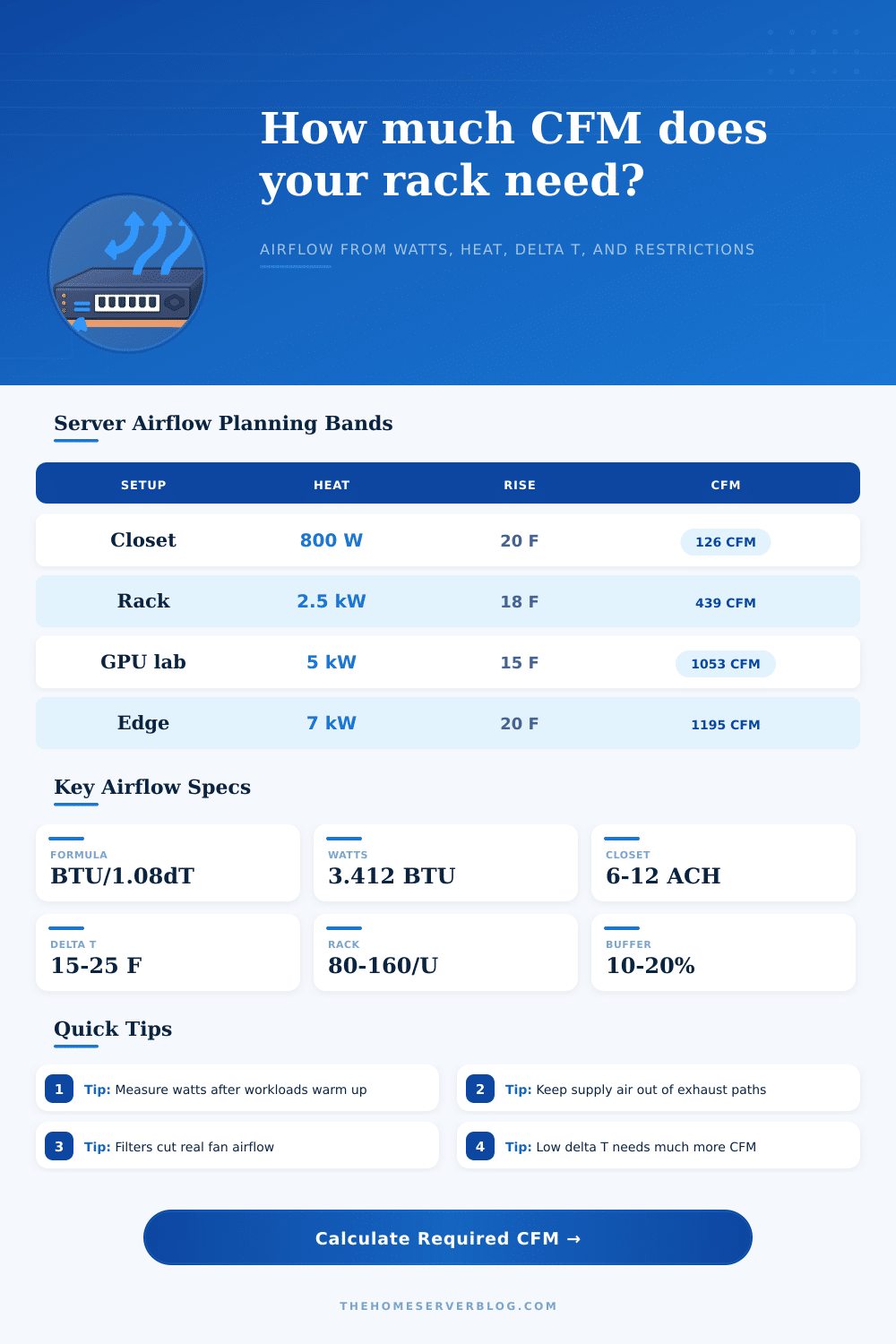
Every watt of power drawn from the IT equipment convert to BTUs of heat within enclosure. A GPU workstation will consume two kilowatts under load; a quiet NAS consumes only sixty watts. Convert that electricity draw to BTUs per hour with a multiplier of about 3.412. Now that you have the amount of heat being generated, it’s simple math. How many cubic feet per minute does it take to maintain temps? The calculator does that work so you don’t have to multiply watts yourself. It takes your measured load and converts it into cubic feet per minute required to stabilize temperature.
But airflow numbers are just numbers until you factor in how much of a temperature increase you can stand. How much warmer does the exhaust air get compared to the supply air coming into space? That’s called the delta T. If the rise in temp is low then huge amounts of air will have to be pushed by big fans which gets louder. There’s a tradeoff here between being acoustically comfortable vs being thermally precise.
If your space is really tightly sealed (like a closet) you can probably handle a higher 18 degree temperature rise with cool supply air. In a living room or open office, you’re likely to get complaints about the fan noise, so you typically want a lower temperature rise. The tool accounts for this temperature difference as well as how much “static pressure loss” there is due to any duct bends, restrictions at grilles, or filters. It helps give you a real number not a theoretical best case.
In reality, planning fails because of restriction. Even a 400CFM fan will push less than that (if even that much) through a sharp duct elbow, then a mesh door, followed by a dusty filter. Flow decreases greatly with static pressure. That’s why the calculator includes an overhead allowance for restrictions. Clean air won’t pass freely through choked pathways without effect.
Plan for growth as well. Systems evolve. Upgrading a power supply or adding another switch adds extra heat load you didn’t expect. A ten to twenty percent buffer allow for system expansion while maintaining enough cooling.
Also take into account the room. In smaller areas such as server closets, air changes per hour become relevant. Because the space is small, air may pool at one end (the ceiling) or another (the floor). For this reason, smaller area need higher turnover rates. Refer to the table on page for some context; it compares the results to typical equipment profiles so that you can see where your numbers fall among normal rack density and beyond.
That is to say, does this make sense? Is it sane? Does it pass the input sanity check? Bottom line? It’s all about moving energy. Cooling can’t make heat dissapears, just move it around.
Start with some honest information by measuring actual power draw instead of nameplate ratings. Minimize short-cycling by separating hot exhaust from cold intake. This will prevent sensor confusion and increase cooling efficiency. Once you know every watt wants its fair share of air, everything else starts falling into place. No more chasing ever-increasing airflow numbers; now you design a system that moves air where it should go.
You should of checked measurements first. Knowing what you’re measuring is half the battle, the other half is knowing how to let physics do the work for you so you can sit back and enjoy your silent lab.