dBm to Watts Calculator
Convert RF power from dBm into watts, milliwatts, voltage, current, EIRP, channel totals, and link-margin context for home lab radios.
Conversion Breakdown
| dBm | Milliwatts | Watts | Common RF Meaning |
|---|---|---|---|
| -100 dBm | 0.0000000001 mW | 0.0000000000001 W | Very weak receiver input or spectrum trace. |
| -70 dBm | 0.0000001 mW | 0.0000000001 W | Usable WiFi client receive level. |
| -30 dBm | 0.001 mW | 0.000001 W | Small lab signal or SDR reference input. |
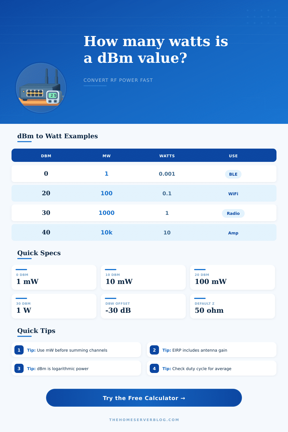
| 0 dBm | 1 mW | 0.001 W | Common RF test level and BLE output class. |
| 10 dBm | 10 mW | 0.01 W | Low-power IoT and sensor radios. |
| 20 dBm | 100 mW | 0.1 W | Typical WiFi conducted output reference. |
| 30 dBm | 1000 mW | 1 W | Small transmitter, radio, or amplifier output. |
| 40 dBm | 10000 mW | 10 W | Higher-power RF stage or bench amplifier. |
| Device Profile | Typical dBm | Linear Power | Planning Note |
|---|---|---|---|
| BLE beacon | -4 to 4 dBm | 0.4 to 2.5 mW | Small output, but battery duty cycle matters. |
| Zigbee sensor | 5 to 10 dBm | 3.2 to 10 mW | Usually mesh range before raw output. |
| LoRa sensor | 14 to 22 dBm | 25 to 158 mW | Regulatory band and duty cycle define use. |
| WiFi access point | 17 to 24 dBm | 50 to 251 mW | Antenna gain changes EIRP quickly. |
| LTE modem | 20 to 23 dBm | 100 to 200 mW | Modems may reduce output as link improves. |
| PTP bridge | 23 to 30 dBm | 200 mW to 1 W | Use path loss and legal EIRP limits together. |
| Formula | Expression | Use | Calculator Field |
|---|---|---|---|
| dBm to watts | W = 10^((dBm - 30) / 10) | Primary conversion | Power value |
| Watts to dBm | dBm = 10 log10(W / 0.001) | Reverse conversion | Input mode |
| dBW | dBW = dBm - 30 | High-power RF references | Breakdown |
| Voltage RMS | Vrms = sqrt(W x ohms) | Bench load calculations | Load impedance |
| Current RMS | Irms = sqrt(W / ohms) | Load and connector checks | Load impedance |
| EIRP | dBm - loss + gain | Antenna-side estimate | Gain and loss fields |
| Project Size | Power Pattern | Primary Check | Secondary Check |
|---|---|---|---|
| Home WiFi survey | 17 to 23 dBm AP output | EIRP after antenna gain | Client SNR at room edge |
| BLE sensor shelf | -4 to 4 dBm bursts | mW and average duty power | Battery load assumptions |
| LoRa driveway node | 14 to 20 dBm bursts | Average watts over duty cycle | Link margin to gateway |
| SDR lab input | -80 to -10 dBm signal | Microwatts or nanowatts | Receiver noise floor |
| 5 GHz bridge | 23 to 30 dBm conducted | EIRP and cable loss | Aggregate channel power |
| RF amp test | 30 to 40 dBm output | Watts and Vrms into load | Heat and attenuator rating |
When measuring radio power, it is essential to understand the difference between decibel-milliwatt (dBm) and watts. A decibel-milliwatt (dBm) measurement represent the power level in a logarithmic scale. Using a logarithmic scale make it easier to measure the gains or losses of signal strength in the system.
A watt measurement represents the actual amount of energy moving through the system. A watt measurement allow people to view the power in a linear scale. As decibel-milliwatt (dBm) measurements uses a logarithmic scale and watts use a linear scale, it is necessary to convert the measurements from decibel-milliwatts to watts to understand the actual power level in the system.
Difference Between dBm and Watts
People use decibel-milliwatt (dBm) units when planning a wireless network or when checking if a radio signal stay within regulatory limits. For example, a WiFi access point may have a power level of 20 dBm, which is equivalent to one tenth of a watt. This measurement dont account for the power that reaches an air through the antenna.
To find the total power of the radio signal being radiated, the Effective Isotropic Radiated Power (EIRP) must be calculated. This is the power level that the regulatory body and neighbors of the radio signal will experience. Using a calculator allow engineers to convert decibel-milliwatts to watts.
The calculator can also help account for antenna gain or the loss of signal through the cables connecting the radio to the antenna. The same rules applies to low power levels, such as Bluetooth beacons. A Bluetooth beacon can emit signals with a power of 0 dBm, which is equivalent to one milliwatt.
If many Bluetooth beacons is deployed in an area using the same channels, the decibel-milliwatt (dBm) values of each beacon cannot simply be added together to determine the total power level of the signals. To find the total power radiated by the Bluetooth beacons, the decibel-milliwatt (dBm) values must first be converted to linear units of watts. The linear watts values can then be added together to find the aggregate power of the signals from the beacons.
Furthermore, each beacon signal has a duty cycle that determines the length of time the signal is on. Peak power and average power measurements are used to determine how long each signal will last and how much thermal load they will add to the enclosure that contain the Bluetooth beacon. Calculations on the receiver side of the radio signal require people to understand the signal power and the noise power.
Noise power comes from the thermal noise floor of the receiver. The noise floor power density is inversely proportional to the bandwidth of the radio signal. The noise floor of the receiver is the thermal noise power plus the noise figure of the receiver.
The signal-to-noise ratio of the signal is the difference between the power of the signal power and the noise floor. This ratio determines whether the data packet will successfuly pass through the radio receiver. Using a calculator for the radio signal allows engineers to calculate the signal power, bandwidth, and noise figure of the system.
By entering these values, engineers can determine if the signal power is higher than the sensitivity of the receiver. This calculation provides engineers with information that will allow them to avoid intermittent drop outs in data transmission between the devices communicating over the radio signal. Impedance is another factor that engineers must consider when working with radio power measurements.
Most radio frequency (RF) systems uses an impedance value of 50 ohms. However, other systems use different impedance values. Even with the same wattage of an RF system, changing the impedance will change the voltage and current values of the system.
Using a calculator, engineers can determine the Root Mean Square (RMS) voltage and RMS current of the RF system. These values can help engineers to determine if the connectors or attenuators in the RF system can handle the power load of the system. If the components will fail under the power load, they will distort or fail when the system is in operation.
There are many other variable to consider in a real project. The loss of signal through the cable will change with the frequency of the signal. The gain of the antenna will change with its mounting height.
The duty cycle will change based off the traffic in the network. These variables will impact the power calculations of the system. The calculator cannot replace measurements with a spectrum analyzer or power meter.
However, using a calculator will remove the friction that engineers experience when performing the calculations. Based on the results of the calculations, engineers can make better design decisions for the RF system, such as reducing the length of the cable or selecting an antenna with a higher gain. Reference tables provide engineers with essential information about the parameters of the system.
The reference tables display the power levels of the devices in each class. Using these tables, engineers can make an educated guess at the power levels used by the devices before they begin to measure the output of the system. The reference tables also show the relationship between the decibel-milliwatts (dBm), watts, and the voltage of the radio signal.
These tables will not replace the measurements that engineers make with a spectrum analyzer or a power meter. However, these tables will help engineers to understand the units of measurement before they begin to make measurements with their instruments. An understanding of the difference between decibel-milliwatts (dBm) and watts is essential for engineers who design and build wireless networks.
Engineers should read the decibel-milliwatt (dBm) values on their instruments because the decibel-milliwatt scale is compact. However, engineers should calculate power in watts when adding power levels, sizing loads in the system, or determining if the system will overheat. Engineers must understand the difference between these two unit of measurement to avoid making error when planning the RF system.
As such, engineers must treat both units of measurement as related to the RF system.