Coaxial Cable Attenuation Calculator
Estimate RF loss through coaxial cable, connectors, splitters, weather margin, and frequency-dependent cable attenuation for home lab antennas, SDR gear, WiFi, LTE, TV, and modem runs.
⚙Fast coax presets
📏Run details
Calculation breakdown
📊Selected cable spec grid
📘Coax attenuation reference
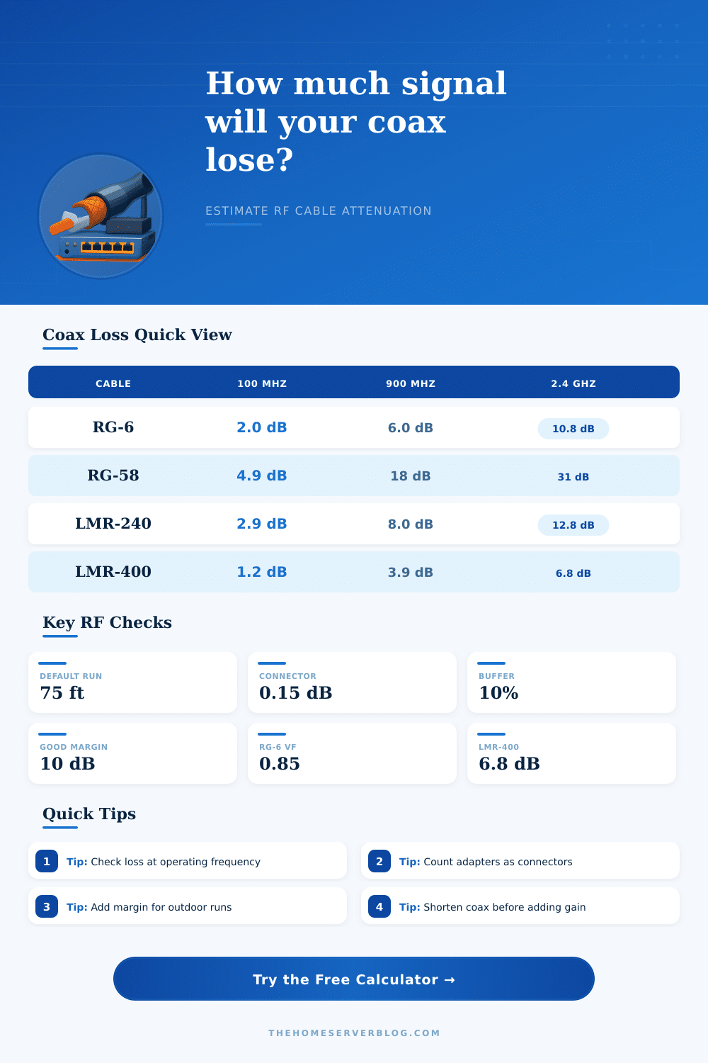
| Cable type | 100 MHz loss | 900 MHz loss | 2400 MHz loss | Best home lab use |
|---|---|---|---|---|
| RG-58/U | 4.9 dB/100 ft | 18.0 dB/100 ft | 31.0 dB/100 ft | Short bench leads and low-frequency SDR patches |
| RG-6 quad shield | 2.0 dB/100 ft | 6.0 dB/100 ft | 10.8 dB/100 ft | TV, modem, satellite IF, and receive-only antenna runs |
| LMR-240 | 2.9 dB/100 ft | 8.0 dB/100 ft | 12.8 dB/100 ft | Moderate antenna feeds where flexibility still matters |
| LMR-400 | 1.2 dB/100 ft | 3.9 dB/100 ft | 6.8 dB/100 ft | Longer VHF, UHF, LoRa, cellular, and WiFi antenna feeders |
| LMR-600 | 0.8 dB/100 ft | 2.5 dB/100 ft | 4.4 dB/100 ft | Low-loss tower or roof runs where bend radius is available |
| Configuration | Typical length | Frequency range | Planning target | Practical note |
|---|---|---|---|---|
| Cable modem drop | 25 to 100 ft | 5 to 1218 MHz | Keep levels in modem spec | Splitters can dominate the loss more than the cable |
| Roof receive antenna | 40 to 150 ft | 50 to 1000 MHz | Preserve weak signal SNR | A mast preamp helps only when placed before the long coax |
| LoRa or UHF feed | 20 to 100 ft | 400 to 915 MHz | Keep EIRP and margin balanced | LMR-400 is often a better fix than extra transmit power |
| 2.4 GHz WiFi feeder | 5 to 40 ft | 2400 to 2500 MHz | Keep coax very short | At microwave frequencies, antenna placement and short coax win |
| Standard or conversion | Value | How this calculator uses it | Why it matters |
|---|---|---|---|
| dB cable loss | dB/100 ft | Interpolates by frequency and scales by run length | Coax loss rises as frequency rises, so cable choice depends on band |
| dBm link budget | power ratio | Adds source power and gain, then subtracts all losses | Shows whether the receiver target still has margin |
| Metric conversion | 1 m = 3.28084 ft | Converts metric length before applying loss tables | Most attenuation tables are published per 100 feet |
| Connector allowance | 0.1 to 0.5 dB | Multiplies connector count by selected connector loss | Adapters, lightning arrestors, and old fittings quietly add loss |
| Project size | Example cable | Approx loss | Secondary result |
|---|---|---|---|
| 25 ft SDR patch at 150 MHz | RG-58 | 1.6 dB plus fittings | Fine for strong local signals |
| 75 ft LTE antenna at 700 MHz | LMR-240 | 5.5 dB plus fittings | Usually needs careful antenna placement |
| 100 ft LoRa feed at 915 MHz | LMR-400 | 3.9 dB plus fittings | Good compromise for roof antennas |
| 35 ft WiFi feed at 2.4 GHz | LMR-400 | 2.4 dB plus fittings | Keep run shorter if possible |
💡Planning tips
Coaxial cable loss are one of the factors that can affect many radio projects. The coaxial cable loss is the value that determine how much of the signal reaches the end of the coaxial cable. Coaxial cables is used in many radio projects to connect an antenna to receiver, for instance, or modem to basement, for instance.
In these applications, coaxial loss will always reduce the signal strength that travel through the coaxial cable. This reduction of signal strength are called attenuation. The value of attenuation can change based on a few different factor.
Coaxial Cable Loss and What Affects It
One of the factors is the frequency of the signal that travel through the coaxial cable. As the frequency of the signal increase within a coaxial cable, the attenuation of that signal increase, as well. Another factor that can impact the attenuation of a coaxial cable is the length of the coaxial cable.
The more longer the coaxial cable, the more attenuation will occur within that cable. Finally, the construction of the coaxial cable can also impact the attenuation of the signal that pass through that coaxial cable. Coaxial cables with certain construction, like foam dielectric and tight braid, will attenuate less than coaxial cables with other constructions.
In addition to the construction of the coaxial cable, each connector on that coaxial cable will cause some loss of signal strength. In these cases, each connector will have a specific loss value that contribute to the total attenuation of the signal. In these cases, a buffer percentage will also be added to the calculations to account for real-world factors like temperature swings and the aging of the coaxial cable over time.
The calculator will provide several data element that allow a radio technician or engineer to understand the performance of the coaxial cable system that they are using. First, the calculator will provide information about the total attenuation of the coaxial cable system. Second, it will provide information about the recieve power in the system.
Third, the calculator will reveal information about the link margin of the system. Finally, the calculator will provide information about the maximum length of the coaxial cable system. There is different types of coaxial cable that can be used in these systems.
LMR-400 cables are used when low attenuation is needed for long distance. The issue with LMR-400 cables is that they is stiff, and this can make routing the cable difficult. On the other hand, RG-6 coaxial cables are more flexible and easier to use.
However, RG-6 cables has higher attenuation than LMR-400 cables. As a result, RG-6 is not ideal for applications that require long distances or high frequences. In order to ensure that the calculations provided by the coaxial cable loss calculator are accurate, certain habit should be followed.
For instance, the calculations should always use the frequency with the highest value for the radio system that is being calculated. Furthermore, every single connector for the coaxial cable should be counted in the calculation. The calculated link margin with the buffer percentage will provide information as to whether or not the coaxial cable run will work for the specified radio system.
If the calculated link margin is positive, then the coaxial cable run will work. If it is close to zero or small, then another option for the coaxial cable may be required.