HomeServerBlog RF path calculator
Earth Curvature Clearance Calculator
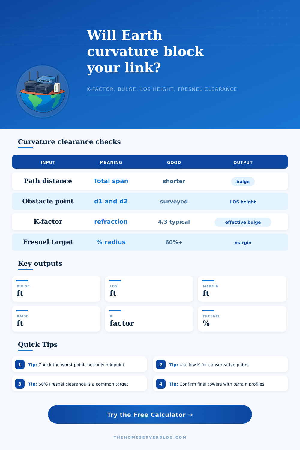
Estimate effective Earth bulge, line-of-sight height at an obstacle, Fresnel clearance margin, and the antenna height increase needed to keep a wireless path clear.
Breakdown
Obstacle location as a share of the full span.
LOS height after subtracting bulge and obstacle.
Selected Fresnel percentage converted to height.
Curvature is largest near the middle of a path.
Height to add at endpoint A if B is fixed.
Height to add at endpoint B if A is fixed.
Higher K reduces apparent curvature.
Pass, watch, or blocked status for the selected target.
The comparison holds your same path, obstacle point, antenna heights, obstacle height, and Fresnel target while only changing the K-factor.
| K-factor | Path condition | Planning use | Effect |
|---|---|---|---|
| 0.67 | Sub-refractive or hot surface layer | Conservative fade planning | More apparent curvature |
| 1.00 | Geometric Earth | No refraction baseline | Standard optical horizon |
| 1.33 | Typical radio atmosphere | Common microwave assumption | Earth appears flatter |
| 2.00 | Strong refraction | Optimistic sensitivity check | Less apparent bulge |
| Fresnel target | Meaning | Typical action | Risk |
|---|---|---|---|
| 40% | Minimum rough clearance | Use only for tolerant links | Higher multipath risk |
| 60% | Common wireless design target | Good default for outdoor links | Balanced |
| 80% | Low fade margin or critical path | Raise towers or move relay | Lower obstruction risk |
| 100% | Full first-zone clearance | Demanding but clean path | Best clearance |
| Obstacle position | Curvature behavior | Endpoint leverage | Check |
|---|---|---|---|
| Near A | Lower bulge | A height helps most | Tree and rooftop clutter |
| One-third span | Moderate bulge | Both ends matter | Terrain and relay mast |
| Midpoint | Maximum bulge | Equal raise is efficient | Long water or valley paths |
| Near B | Lower bulge | B height helps most | Destination roofline |
| Output | Formula role | Positive means | Negative means |
|---|---|---|---|
| Earth bulge | d1 x d2 / (1.5 x K) | Curvature height to subtract | Not applicable |
| LOS height | A + slope x d1 | Antenna chord is above baseline | Endpoint model is invalid |
| Actual clearance | LOS - bulge - obstacle | Physical space above object | Object penetrates sightline |
| Margin | Actual - Fresnel target | Target is met | More height is needed |
On a rooftop, you stare out over a valley at another building. There’s nothing in your line of sight blocking your way. As your eyes connect the dots, path looks clear. Just because you can see it doesn’t mean your signal will reach it.
That’s why wireless projects fail: they makes assumptions. They think that what their eyes see is also true for radio waves. But there’s an invisible bulge under your feet called the earth, which deflects your line of sight. It only cares about geometry and atmospheric refraction, not your visual confirmation. When you enters the height and distance into the calculator, it run the math, and eliminates guesswork as to whether some distant ridge will block your signal.
Why You Can See It But Your Signal Cannot Reach It
In flat space, radio waves moves in a straight line. But they don’t, they bend just a little bit because of atmosphere. Typically, they follow a path that’s about four-thirds the radius of the earth. That gives you a longer effective horizon, true…but it also creates a dip in the middle of your link where the path curves deeper toward the earth then you’d expect based off the geometry of antennas.
On a five-mile link, you’ll never notice this. You can probably safely ignore it altogether. But if you’ve got a twelve-mile backhaul, well, suddenly that bump becomes a real problem. In fact, on a twelve-mile backhaul, the bump will be about 15-20 feet higher then the imaginary straight line between your two antenna. And when there’s a roofline or tree halfway along your span, those extra feet make all the difference between a solid, full-strength connection and one with dropped packets every time it rains or gets realy hot out. Any link over two or three miles long has enough curvature that you must take it into account.
The tool lets you input distance from antenna A to the specific obstacle you are worried about. People get tripped up because they think it always assumes the issue is right down the middle. But maybe there’s a ridge a third of the way along the route where ground is high and curvature bulge is low. The calculator takes the straight line height difference between the two antennae, minus the effective bulge of the earth at exactly that spot along the route. Then it see how much clearance is left, if the answer is positive, you have physical clearance. If it is negative, you’re out of luck.
Beyond mere physical obstruction, there’s another element: the Fresnel zone. Radio waves requires some breathing space, a bit like a pipe that carries your energy; called the Fresnel zone. It is essentially an oval area surrounding the direct line-of-sight path. Ideally, you don’t want any obstructions (buildings, trees) touching the boundary of this Fresnel zone. To ensure you have adequate clearance, one commonly-used standard say you must maintain at least 60 percent of the first Fresnel zone clear. Using your path split and frequency, the calculator estimates radius of the first Fresnel zone and determines if you’re above or below this standard. If you’re not, it will tell you by how much you must increase height of your antennas. This provides more than a simple pass/fail verdict; it gives you a concrete construction specification. From “will it work” to “how high does my tower has to be,” it moves the discussion into tangible territory.
The K-factor accounts for the fact that actual curvature of the earth varies depending on atmospheric conditions. For example, the K-factor of 1.33 represents normal (typical) atmospheric bending. On hot days, when the ground heats up strongly, there is less refraction and the earth look more curved because it appears smaller. That reduces your clearance margin. To be on the safe side, conservative planners will model their links using a lower K-factor so that they’ll work even during bad weather. As table on the linked page shows, varying the K-value alters the apparent size of bulge. If you’re at the limit of a long path, it could of been worth verifying those extremes.
Managing unseen obstacles, That’s line-of-sight design. The earth’s curvature and the Fresnel zone aren’t visible to you, yet they determines whether it will work for you as much as that brick wall does. These are all of those unseen variables that, when quantified, take the guess out of your site survey. It stops being “I can see it,” and starts being “I know I have X feet of clearance.” When that signal doesn’t do what you want after mounting the hardware, this change of thought process keeps you from making an expensive mistake.