Grounding Conductor Size Calculator
Size equipment grounding conductors and bonding jumpers from circuit amps, conductor material, fault current, clearing time, installation method, run length, temperature rating, parallel raceways, margin, and code profile.
Grounding conductor result
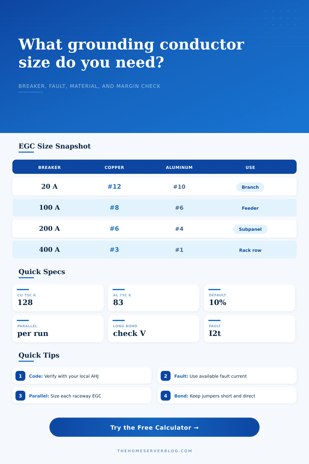
| Breaker or fuse | Copper EGC | Aluminum EGC | Typical home lab use |
|---|---|---|---|
| 15 A | #14 AWG | #12 AWG | Small receptacle branch |
| 20 A | #12 AWG | #10 AWG | Dedicated server branch |
| 60 A | #10 AWG | #8 AWG | Small subpanel feeder |
| 100 A | #8 AWG | #6 AWG | Rack or shop feeder |
| 200 A | #6 AWG | #4 AWG | Detached lab panel |
| 400 A | #3 AWG | #1 AWG | Parallel service gear |
| Material and rating | k factor used | Thermal meaning | Planning note |
|---|---|---|---|
| Copper 60°C | 115 | Lower thermal limit | Older terminals or insulation limits |
| Copper 75°C | 128 | Middle thermal limit | Common equipment-terminal planning value |
| Copper 90°C | 143 | Higher thermal limit | Use only when permitted for thermal check |
| Aluminum 75°C | 83 | Needs more area | Confirm antioxidant and lug listing |
| Installation type | Multiplier | Why it changes | Field check |
|---|---|---|---|
| Raceway EGC | 1.00x | Baseline equipment grounding conductor | Check raceway continuity |
| Cable assembly | 1.00x | Integral EGC follows cable listing | Match cable markings |
| Tray bonding | 1.10x | Long exposed path and joints | Bond tray sections |
| Service bonding jumper | 1.25x | Main bonding duty is more critical | Use service rules |
| Outdoor feeder | 1.15x | Corrosion and detached-structure exposure | Protect terminations |
| Scenario | Breaker | Fault study | Likely minimum |
|---|---|---|---|
| Server closet branch | 20 A | 5 kA at 0.08 s | #12 copper EGC |
| UPS rack feeder | 30 A | 8 kA at 0.10 s | #10 copper EGC |
| Lab subpanel | 60 A | 10 kA at 0.10 s | #10 copper EGC |
| Rack row feeder | 200 A | 22 kA at 0.05 s | #6 copper EGC |
| Parallel service gear | 400 A | 42 kA at 0.05 s | #3 copper each run |
What about the most potentially hazardous part of an electrical system? The grounding conductor is not what gets much attention. Sure, the hot conductors is where the current goes to power lights and servers. But when there’s a fault, that grounding conductor saves your life. If it’s undersized, it’ll fail and expose you to danger. To be safe, make sure the conductor are sized appropriately to provide low resistance path for the fault current.
The page contains a calculator that lets you enter the breaker ratings, the fault current, and the clearing time, which will tell you exactly how large the ground should of be. No more guesswork. And knowing why you’re using these numbers makes everything safer.
Why Ground Wire Size Matters
The first is the circuit protection rating. This establish the minimum allowable wire size based off code tables. A four-hundred-amp service entrance need a different size ground than a twenty-amp branch circuit. That’s because it has to have big enough wire to carry fault current up to the breaker without melting. But many folks pick this from the table, choose the wire, then walk away. That works in a closet at home for little stuff. When things gets long, or fault currents is high, it doesn’t work.
The key information for this consists of clearing time and fault current inputs. Fault current is amount of electricity flowing in the fault. Clearing time is how long it takes for the fuse or breaker to open the circuit. It’s measured in a few milliseconds. The calculator will run an adiabatic calculation based on those parameters. Basically it asks: Can this wire withstand heat produced by the fault? If you have a huge fault current (tons of amps), but it only lasts a tiny bit longer until the breaker opens, then there is dramatic thermal stress. The wire may pass a simple ampacity check, but not be able to withstand the thermal shock. The tool will determine whether physical material itself can handle the surge in energy.
The other complicating factor here is material selection. For instance, copper is most commonly used as it conducts very well and resists thermal stress well. While aluminum is lighter and less expensive, its cross-sectional area must be proportionately bigger to conduct same amount of current. Also, aluminum will oxidize at the terminals. The calculator allows you to specify various materials that has their own k-factor, or thermal property of the material. Then it will let you know whether to upsize the wire by changing from copper to aluminum. That way you won’t accidental downsize aluminum grounding wires using copper tables.
Wire size is also dependent upon installation. Does it have to be installed as a bonding jumper? Is it in an unattached building? There are different factors such as these, and the calculator use multipliers to match. For example, if it’s a service bonding jumper, it considers this to carry critical duty. And it also considers parallel runs. Each run of conduit receives its proper size ground instead of being split between two or more conduit. This is another code violation we commonly see. This tool will help prevent that.
Add extra insurance of 10% or even 20% for an added safety margin. If you think there might be some unknowns with future upgrades or your fault study, this adds that as a buffer. For average sizes, those are what the reference table lists on the page. The calculator digs deeper into how breaker curve, your fault current and wire type work together. It examines all these factors together, because grounding isn’t about buying cheaper wire. It’s about having a low impedance path to ground when everything else fails.
When you sized it correctly, everything hums along quietly and you never know it. Actualy, it works fine.