Network Cable Length Calculator
Plan Ethernet horizontal runs with patch leads, slack, bend radius, structured cabling limits, and permanent link versus channel checks.
Structured Cable Length Results
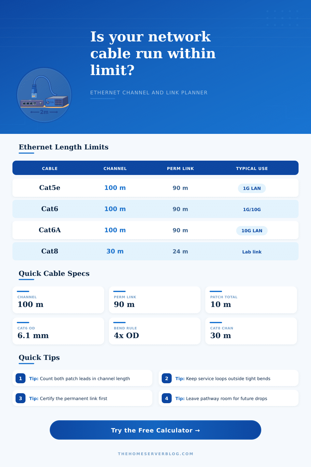
Ethernet category planning limits
| Category | Channel limit | Permanent link | Typical home lab use |
|---|---|---|---|
| Cat5e | 100 m / 328 ft | 90 m / 295 ft | 1 GbE access drops and short PoE devices |
| Cat6 | 100 m / 328 ft for 1 GbE; shorter 10 GbE planning | 90 m / 295 ft | General drops, APs, cameras, and light 10G runs |
| Cat6A | 100 m / 328 ft | 90 m / 295 ft | Preferred copper choice for 10 GbE structured runs |
| Cat7 / Class F style | 100 m / 328 ft planning length | 90 m / 295 ft planning length | Shielded specialty cabling where compatible hardware is used |
| Cat8 | 30 m / 98 ft | 24 m / 79 ft | Short data-center or lab switch-to-server links |
Channel versus permanent link components
| Basis | Counted cable sections | Best for | Calculator behavior |
|---|---|---|---|
| Permanent link | Patch panel or jack to work-area outlet | Certifying the installed fixed cabling | Checks routed horizontal length plus fixed-cable slack only |
| Channel | Equipment cord, permanent link, and work-area cord | Checking the live end-to-end Ethernet path | Adds both patch leads to the permanent link length |
| Bulk pull length | Horizontal run, service loop, pathway factor, buffer | Cutting or ordering installed cable | Excludes replaceable patch cords from the bulk cable total |
| Patch allowance | Telecom-room lead plus work-area lead | Preserving room under the 100 m channel limit | Warns when patch leads consume too much channel budget |
Common structured cabling scenarios
| Scenario | Typical runs | Cable choice | Length focus |
|---|---|---|---|
| Home office dual drop | 2 to 4 | Cat6 or Cat6A | Patch lead allowance and wall-drop slack |
| Ceiling access point | 1 per AP | Cat6 PoE-ready | Service loop above tile without tight coils |
| Camera soffit run | 1 per camera | Outdoor-rated Cat6 | Detours, drip loops, and equipment-room patching |
| 10G lab backbone | 1 to 4 | Cat6A | Keeping a full 100 m channel margin |
Bend radius and cable diameter guide
| Cable family | Typical OD | 4x bend radius | Planning note |
|---|---|---|---|
| Cat5e UTP | 5.3 mm / 0.21 in | 21 mm / 0.83 in | Flexible for older gigabit drops |
| Cat6 UTP | 6.1 mm / 0.24 in | 24 mm / 0.96 in | Good default for home structured cabling |
| Cat6A UTP | 7.4 mm / 0.29 in | 30 mm / 1.17 in | Needs larger managers and gentler turns |
| Cat8 shielded | 8.5 mm / 0.33 in | 34 mm / 1.34 in | Short links with careful pathway control |
When you are installing network cables, you must plan the total length of the network cable that will be install. The path from the patch panel to the network drop point is rarely a straight line. It is necessary to account for the length of the horizontal cable run, the service loops at each end of the link, and two patch cords that will complete the link from the patch panel to the network device.
The length of the patch cords are important to account for in the planning stage of the installation; if you dont account for the length of the patch cords, you may find that you do not have enough cable length to complete the installation. The horizontal cable run is the length of the permanent link between the switch and the patch panel; it is the longest length of network cable in the installation. However, there are two service loops in the installation that must be accounted for in the length planning.
How to Plan Network Cable Length
One service loop is required in the telecom room to allow for dressing of the network cable into the rack. The other service loop is required at the work area to allow for the potential re-termination of the network cable. Both service loops is included in the length of the installed network cable.
The total channel is the length of the link between the patch panel and the network device. The total channel consists of the permanent link between the patch panel and the network device, the length of the patch cord between the switch and the patch panel, and the length of the patch cord between the network device and the patch panel. The lengths of the patch cords should be measured separately from the length of the permanent link; the patch cords will reduce the length available for the permanent link if the patch cords is considered an afterthought during installation.
The length of the pathway in which the network cable will be installed may impact the total length of network cable that is required. The network cable may have to make vertical drops into the network device boxes. The network cable may have to make detours around beams or through pull boxes if the network cable will be installed within a conduit.
These detours may require the installation of a routing multiplier to the length of the network cable. Using a routing multiplier will prevent you from purchasing network cable based solely on the blueprint to the location, as the blueprint will not show the vertical drops or detours that must be made in the installation of the network cable. The bend radius of the network cable is the radius of the turn of the network cable that will be installed.
The bend radius is important to consider in that it will protect the network cable from any damage that may be caused by tight turns of the network cable. For instance, Cat6A network cable has a larger outer diameter than Cat5e network cable. Therefore, a Cat6A network cable has more space required to make turns than a Cat5e network cable.
Additionally, if a network cable has many turns of 90 degree, the bend radius will be larger. You should ensure the bend radius to provide enough space for the minimum inside radius for the network cable. The length of network cable that is installed may have different length limits based off the category of the network cable.
For instance, Cat8 network cable is only designed to allow for very short link. On the other hand, Cat6A network cable is capable of transferring data at ten gigabits per second over a one-hundred-meter length channel. Therefore, the distance between the network patch panel and the network device will impact which category of network cable is purchased and installed.
A buffer length may be added to the length of network cable that is purchased if the installation is a retrofit installation. In this situation, the network cable may have to travel through various pathways, possibly even through the cables that are already installed within the wall boxes. The length of the network cable that will be purchased will have a buffer of ten or fifteen percent of the total length of the network cable.
This length will be allowed for the retrofit installation; it wont be considered part of the length of the channel that the network cable will travel. It is important to ensure the difference between the buffer length and the length limit of the network cable. The length of the permanent link and the length of the network channel are two different measurements of the same installation.
The length of the permanent link is the length of the network cable that is installed between the patch panel and the network device; it is one portion of the total length of the network channel. The length of the network channel is the total length of the installation, from the switch to the network device. It is common for network technicians to test the length of the permanent link to identify potential problems in the length of the installed network cable.
However, the length of the network channel is also considered in relation to the active network equipment that is used to communicate with the network device. The service loops that are installed in the network installation can create problems in relation to the bend radius of the network cable. For instance, the service loop that can be installed within the rack is useful for network cable dressing.
However, if the network cable is coiled in the service loop, the radius of the network cable may be too large for the bend radius of the network cable. Additionally, the service loop at the network device can also lead to problems if the network cable is forced to make a turn at the network device. In this situation, the bend radius at the network device must meet the radius target of the calculated length of the network channel.
The length of the network cable that should of been purchased can be planned by considering each of the components of the network installation separately. For instance, the length of the network cable, the length of the patch cords, the routing of the network cable, and the length of the service loops should each be considered separately. Each of these components of the network installation has its own length constraints.
If these components are not considered separately, the errors in length will not be discovered until the network cable fails to pass the installation test.