Kubernetes capacity planning
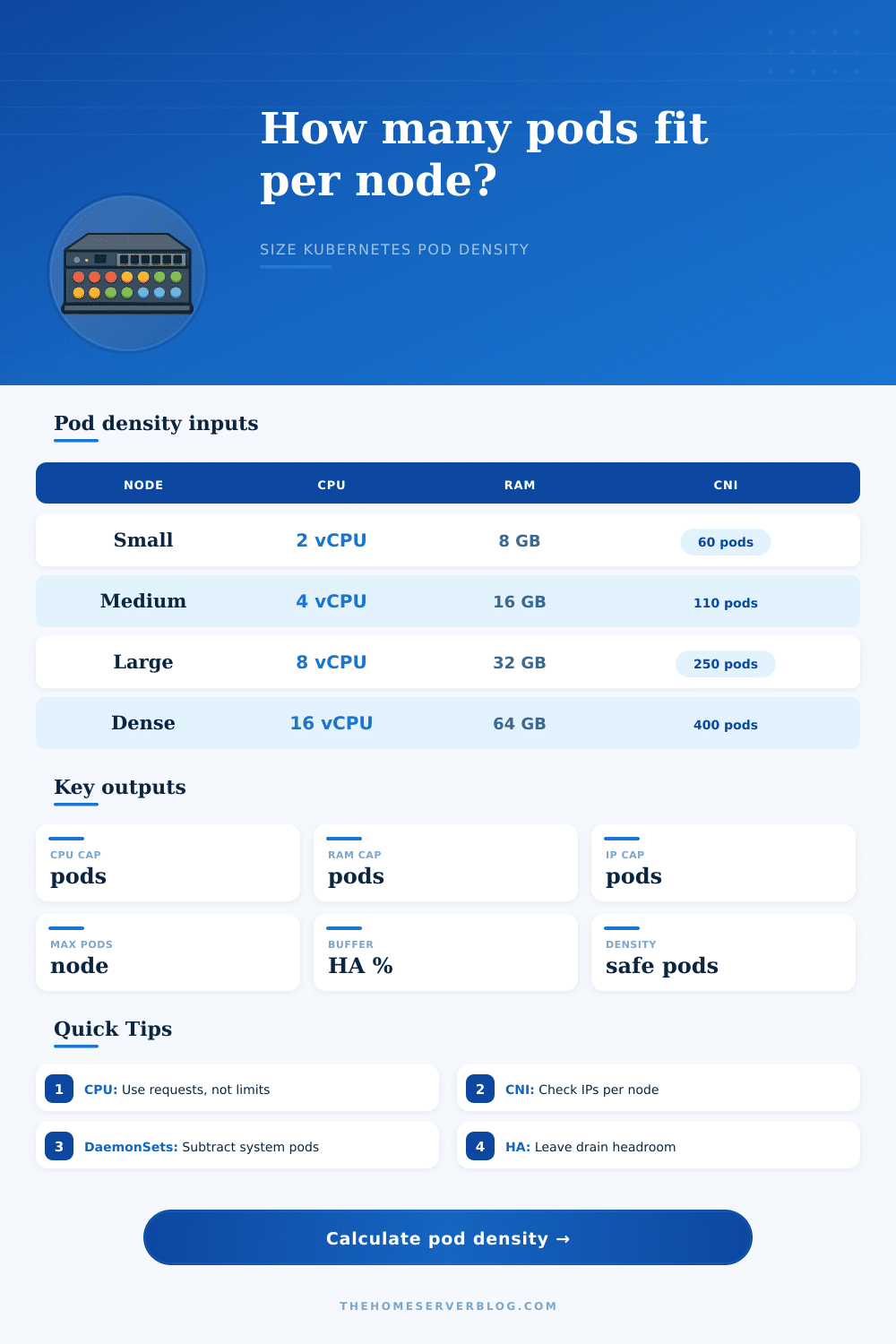
Pod Density Per Node Calculator
Estimate safe Kubernetes workload pods per node from CPU requests, memory requests, maxPods, pod IP supply, DaemonSet pods, kube/system reserve, CNI limits, overhead, and HA drain buffer.
Constraint breakdown
Node utilization at recommendation
K3s Mini Node
2 vCPU, 4 GB RAM, lower maxPods, small DaemonSet footprint, useful for edge and home lab clusters.
EKS Prefix Mode
Higher IP supply than classic secondary-IP ENI mode, but still keep kubelet maxPods and subnet capacity aligned.
Calico Bare Metal
Overlay or routed pod networking can remove cloud ENI pressure, making CPU and memory the usual limits.
Dense Services
Small requests can push high pod counts, so kubelet, conntrack, DNS, logging, and policy scale need attention.
| Average workload pod | 2 vCPU / 8 GB | 4 vCPU / 16 GB | 8 vCPU / 32 GB | 16 vCPU / 64 GB |
|---|---|---|---|---|
| 50 mCPU / 128 MiB | 28-45 pods | 56-90 pods | 100-180 pods | 180-360 pods |
| 100 mCPU / 256 MiB | 14-28 pods | 28-56 pods | 56-112 pods | 112-224 pods |
| 250 mCPU / 512 MiB | 6-12 pods | 12-24 pods | 24-48 pods | 48-96 pods |
| 500 mCPU / 1 GiB | 3-6 pods | 6-12 pods | 12-24 pods | 24-48 pods |
| 1 vCPU / 2 GiB | 1-3 pods | 3-6 pods | 6-12 pods | 12-24 pods |
| Constraint | Calculator treatment | Healthy target | Warning sign |
|---|---|---|---|
| CPU requests | Node vCPU minus kube reserve and runtime overhead, divided by average pod request. | Keep requested CPU below allocatable CPU with burst room. | High throttling, noisy neighbors, long queues. |
| Memory requests | Node RAM minus reserve and overhead, divided by average pod memory request. | Leave room for page cache and eviction thresholds. | OOMKills, eviction pressure, kernel memory pressure. |
| Pod slots | Kubelet maxPods minus DaemonSet pods. | Leave some empty slots for drains and rollout surge. | Pods pending even with free CPU and RAM. |
| Pod IPs | Lower of IPs per node and ENI/CNI limit, minus DaemonSet pods. | Subnet and per-node IP supply exceed maxPods. | IP allocation errors from the CNI plugin. |
| HA buffer | Reduces the binding limit after resource and network limits are found. | 15-30% for production, more for small clusters. | Node drain cannot reschedule without scaling. |
| CNI / mode | Main density limiter | Typical node limit | Planning note |
|---|---|---|---|
| AWS VPC CNI secondary IP | ENI and IPv4 addresses per instance type | Often 29-110 pods | Instance choice can matter more than CPU for small nodes. |
| AWS VPC CNI prefix delegation | Prefixes, maxPods, subnet size | Often 110-250 pods | Greatly improves IP density but subnet planning still matters. |
| GKE VPC-native | Secondary range and max pods per node | Commonly 32-256 pods | Choose pod CIDR sizing before creating node pools. |
| Azure CNI | VNet IP allocation per node and pod | Often 30-250 pods | Subnet exhaustion is a common hidden cap. |
| Azure CNI overlay | Kubelet maxPods, CPU, memory | Often up to 250 pods | Overlay mode reduces VNet IP pressure. |
| Calico overlay | CPU, memory, kubelet, policy scale | 110-500 pods | IP pool size is flexible; policy cost may dominate. |
| Calico BGP routed | Route scale, CPU, memory | 110-500 pods | Works well for bare metal when routing is designed cleanly. |
| Cilium overlay | CPU, memory, BPF map scale | 110-500 pods | Watch service, policy, and conntrack-like map pressure. |
| Cilium native routing | Routing and BPF map scale | 110-500 pods | Good density when underlay routing is predictable. |
| OpenShift OVN-Kubernetes | Cluster defaults, node resources, SDN scale | Often 250 pods | Use platform-tested density targets for production support. |
In Kubernetes you don’t typically fail due to lack of disk space; you break capacity planning. Usually system falls over when you hit a limit. This might be too many pods for the kubelet scheduler to manage without stalling, too many connections and IP addresses for kernel, or who knows what. Memory and CPU are tangible resources that you can measure on a dashboard; it’s understandable that you fixate on them.
Pod density is a complex constraint with software and networking limits that will bite you long before you hit any hardware limit. It’s easy to guess wrong about whether you’re more likely to have a connectivity bottleneck or compute bottleneck, but the calculator above spares you. Just plug in your workload profiles and node specs, and let the calculator do the math.
How to Plan Your Cluster Space
So let’s start with what determines all of this: your average pod request size. Unless your service is really light (e.g., uses only 128 MB of RAM and 50 millicores), it will take up a whole CPU core and chunk of RAM. This means that soon enough, you’ll be out of resources for new pods before you get to far. In other words, the limit here is simple arithmetic.
On the other hand, if your service is truly tiny (e.g., uses only 128 MB of RAM and 50 millicores) then you could potentialy fit hundreds of them on a node. And this is where the hidden limits come into play. Each pod require some space in the kubelet’s tracking structures, a spot in the kernel’s network namespace table, and an IP address. You may not have used even half of machine’s CPU. However, you may have already exceeded the `maxPods` limit or reached maximum number of Pod IPs. This means you cannot schedule any more containers.
There is a quiet cost to density, and that silent tax are DaemonSets. Nearly all clusters deploy monitoring sidecars, security scanners, CNI plugins, logging agents, etc. These are deployed as DaemonSets. They’re pods that begin running on each node before any application code lands. In a tight environment with limited IPs, a handful of system pod could grab half your capacity on a small node.
To compensate, the tool lets you subtract out these fixed costs from your overall allowance. This is an important tweak. If you don’t account for system pods, you’ll over provision nodes that look empty on paper but are actualy stuffed with operational overhead.
The other part of the problem is that network config is crazy-varied by provider, as well. Cloud providers typically use some form of CNI plugin which tie pod IPs to some sort of underlying subnet/subnet/network interface. For example, AWS VPC CNI constrains pods based off the number of secondary IP addresses supported per ENI (Elastic Network Interface) and the max number of ENIs supported for each instance type. Even if you’ve got a huge server with oodles of RAM, if it’s only got two ENIs that support limited numbers of IPs, then your pod count gets capped pretty soon.
Moving to overlay or prefix delegation mode fundamentally changes this calculation, removing the hard limit of network addresses and instead letting pod count be constrained again by things like CPU/memory. The page has nice reference tables that detail all this out, exactly where various CNIs move the bottleneck from network address back to, say, memory/CPU.
Finally, leave some space for chaos. Leave headroom in your cluster for software updates, moving nodes, and unexpected changes in size. Packing your nodes to 100% usage means the scheduler will have to evict other pods under any sort of maintenance activity, which leads to cascading failures. By setting a 20+% HA buffer or higher, you ensure that when a node goes down, its workload can be migrated to nearby nodes without landing in pending state or causing OOM kills. It’s not only about stability, but also maintaining predictable latency even in the face of disruptions.
What I’ve found over time though is it’s largely a question of knowing what those numbers mean. How thin do you slice? Memory and CPU are continuous resources. Pods are discrete slots with an upper bound. IP addresses are finite leases. You want to keep all of them in balance and not have one dictate your scaling behavior too soon. Let the tool tell you which is the binding limit, then set your node pool strategy around that.
Are you bottlenecked by the number of connections or pod IPs? Is your environment such that bigger nodes are cheaper then smaller nodes? More big nodes or lots of little nodes? Capacity planning isn’t a race to maximum density for its own sake. It’s about never getting surprised when the network’s run out of room way before the server is.