HomeServerBlog electrical capacity planner
Power Factor Correction Calculator
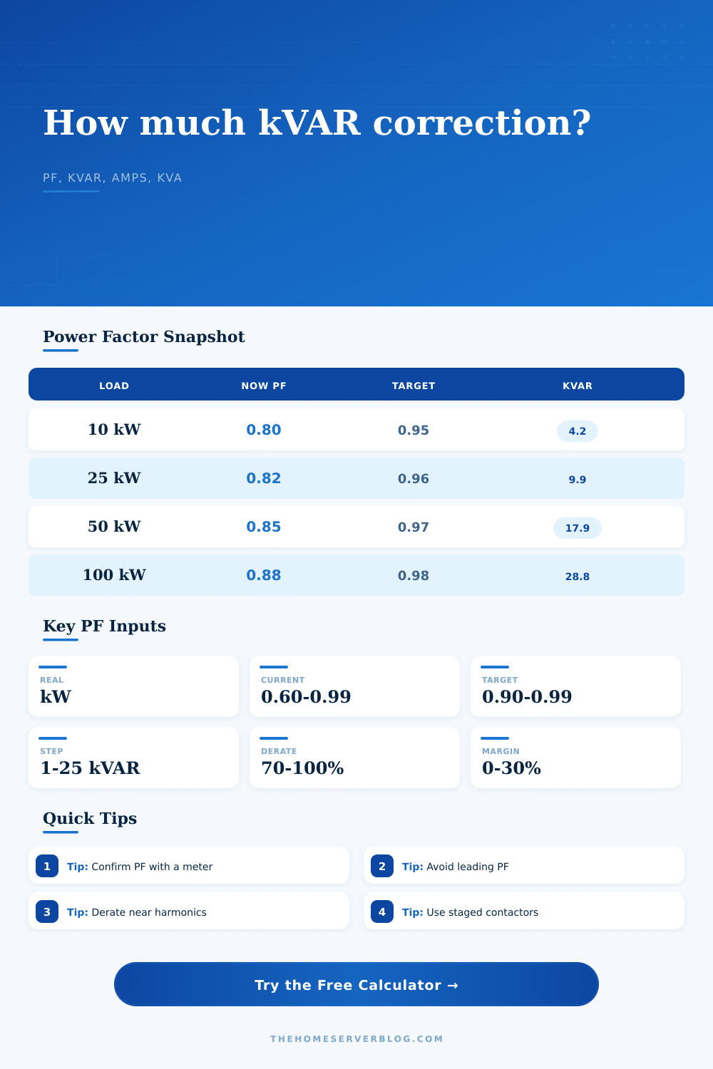
Estimate capacitor kVAR, apparent power reduction, line current change, rounded bank steps, harmonic derate impact, utilization reserve, and planning margin for server rooms, workshops, pumps, compressors, and mixed home lab loads.
▦Power factor presets
⚙Load and correction inputs
Correction breakdown
Step and method check
▣Live correction details
Apparent power at the entered current PF.
Apparent power at the selected target PF.
Reactive correction before bank allowances.
Rounded bank size divided by the selected step.
▥Correction method grid
☰Power factor reference tables
Target PF sizing factors
| From PF | To 0.90 | To 0.95 | To 0.98 |
|---|---|---|---|
| 0.70 | 0.536 kVAR/kW | 0.692 kVAR/kW | 0.886 kVAR/kW |
| 0.75 | 0.398 kVAR/kW | 0.553 kVAR/kW | 0.748 kVAR/kW |
| 0.80 | 0.266 kVAR/kW | 0.421 kVAR/kW | 0.616 kVAR/kW |
| 0.85 | 0.135 kVAR/kW | 0.291 kVAR/kW | 0.485 kVAR/kW |
Typical load PF ranges
| Load type | Typical PF | Correction style | Watch item |
|---|---|---|---|
| Server UPS input | 0.90-0.99 | Usually minimal | Harmonics and rectifier front end |
| Induction motors | 0.70-0.88 | Fixed or automatic | Overcorrection when lightly loaded |
| Pumps/compressors | 0.72-0.90 | At-load or staged | Starting sequence and cycling |
| VFD panels | 0.88-0.98 | Detuned bank | Resonance and capacitor heating |
Capacitor step planning
| Bank size | Fine steps | Common steps | Best use |
|---|---|---|---|
| Under 10 kVAR | 0.5-1 kVAR | 1-2.5 kVAR | Small panels and light shops |
| 10-50 kVAR | 2.5 kVAR | 5 kVAR | Mixed workshop loads |
| 50-150 kVAR | 5 kVAR | 10-25 kVAR | Feeder banks |
| 150+ kVAR | 10 kVAR | 25-50 kVAR | Service-level correction |
Current reduction examples
| Current PF | Target PF | kVA drop | Current drop |
|---|---|---|---|
| 0.75 | 0.90 | 16.7% | 16.7% |
| 0.80 | 0.95 | 15.8% | 15.8% |
| 0.85 | 0.97 | 12.4% | 12.4% |
| 0.90 | 0.98 | 8.2% | 8.2% |
⚠Practical sizing tips
A kilowatt is how you measure the actual work your equipment performs. But then there’s the reactive part, pulled by things with magnets like transformers and motors. That’s the apparent power, and the electrical system must manage it to. Power factor measures this gap, and failing to account for it mean wasted capacity, unnecessarily big wiring, and fines on your utilities bill.
Plug in some details of your loads into the calculator above and let it do the trigonometry. This saves you from having to do it yourself while giving you an idea of just how much of a capacitor bank will fit at your location. But that’s where the real power (in kW) comes into play; it doesn’t matter if your wire is inefficient; the input will be roughly the same. Likewise, you’ll need the present power factor which can be read from either a good meter or on your utility bill.
How to Use the Power Factor Calculator
If it’s 0.80, then it means that you’re drawing 25 percent more current than the task actualy needs. This excess current will heat up your wires. And it will decrease capacity of both your generators and your transformers.
The solution here isn’t to change the physical properties of the motor, instead, it’s to provide the required reactive power at the local level, not leaving it for the utility grid to deal with. This is a balancing act of targeting the proper power factor. While the closer to.98-.95 you push (increasing your line current), the more line current you free up. That means you may be able to skip an upgrade on a feeder circuit. But you don’t want to go too far the other direction either. A factor of one or greater can cause voltage rise, and even lead to unstable conditions within the local grid. By adjusting the target, the tool lets you see the drop off in line current and kVA; so that you’re getting just close enough to satisfy the utility without risking overcorrection.
Capacitor banks are also threatened by harmonics. LED lighting, variable frequency drives and switch-mode power supplies all produce a distorted current waveform if they’re on the same bus. Plain capacitors can start resonating with the system inductance, which creates hot spots that will distort voltage even more while destroying the bank. This is accounted for in the calculator’s harmonic derate input. This input lowers output capability of the capacitors, so you must purchase a bigger bank to get the same correction. It’s a small price to pay for peace of mind and reliability. Sometimes the only way to go safely here is with detuned reactors, and the calculator takes that derating into account when it recommends your final kVAR.
Real-world considerations limit the physical size of the bank. Actual capacitors are only available in certain standard steps; that is, you don’t obtain the precise theoretical kVAR value calculated by the equation. Instead, it rounds up to the next available step to reach your target. It also includes a safety margin for measurement error and capacitor aging. Loads vary by season and capacitors loses their capacitance over time. Having a bit more reactive power capacity rather than being at risk of running short within a year is preferable. You want a power factor that doesn’t creep back downward over time as the equipment ages.
It also has some handy reference tables on the page for those who need a quick sanity check. See what it takes to go from 0.80 to 0.95 in terms of kVAR per kW. Or how much current drops when you correct a 0.75 load. That will help you catch any mistakes before you place the order. If you find yourself way off base with your calculated bank size compared to what the table shows, double-check your inputs for voltage and phase. It makes a big difference whether you’re calculating single phase or three phase. The kVAR required stays the same, but the current value does not. A commonly made mistake that throws off the amp reduction numbers is getting the phase incorrect.
In conclusion: PFC isn’t just penny-pinching on the electricity bill; it’s about having capacity AND being efficient. By lowering heat stress on your transformers and conductors, it extends the life of your electrical infrastructure. You can add additional load without upgrading your service entrance. There are some small details involved, like respecting harmonic distortion and carefully measuring. But when you know what those numbers mean, it stops being guesswork. Instead, it becomes engineering a long-lasting solution for a clean, capable electrical system.