HomeServerBlog power transfer planner
Transfer Switch Sizing Calculator
Estimate ATS or STS amp rating, kVA, switch frame size, inrush exposure, generator fit, bypass need, continuous derate, and future growth for home labs and small equipment rooms.
Calculation breakdown
Capacity status
Load amps before growth and continuous derate.
Design kW as a share of generator rating.
Usable amp headroom after derate.
Momentary motor-weighted apparent load.
| Frame | Typical voltage | Use case | Planning note |
|---|---|---|---|
| 30 A | 120/240 V 1P | Small critical-load panel | Useful for router, modem, NAS, and a few outlets. |
| 60 A | 120/240 V 1P | Home lab subpanel | Often enough for light rack and network loads. |
| 100 A | 120/240 V 1P | Whole lab or small office | Check feeder, neutral, and generator breaker coordination. |
| 200 A | 208/480 V 3P | MDF or small data room | Often paired with maintenance bypass. |
| 400 A+ | 208/480 V 3P | Larger equipment room | Manufacturer submittals and fault ratings matter. |
| System | Formula | Example | Watch item |
|---|---|---|---|
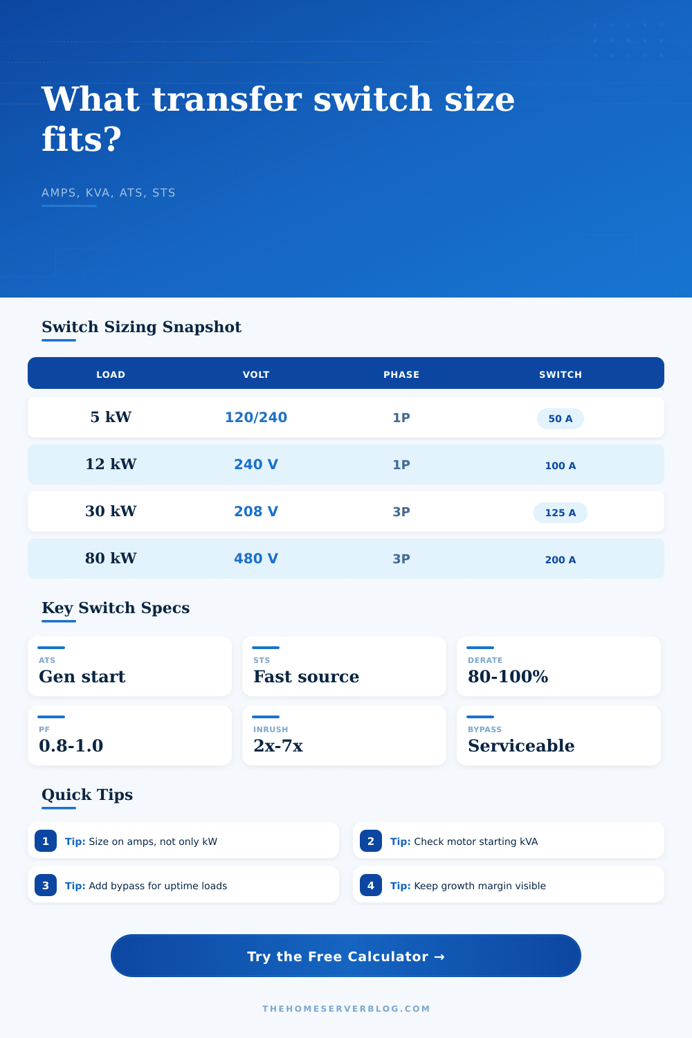
| 120 V 1P | kW x 1000 / V / PF | 5 kW at PF .9 = 46 A | Branch circuit and neutral loading. |
| 240 V 1P | kW x 1000 / V / PF | 12 kW at PF .92 = 54 A | Continuous load derate. |
| 208 V 3P | kW x 1000 / 1.732 / V / PF | 30 kW at PF .9 = 93 A | Line-to-line voltage assumption. |
| 480 V 3P | kW x 1000 / 1.732 / V / PF | 80 kW at PF .9 = 107 A | Control power and neutral plan. |
| Requirement | Recommended feature | Best fit | Tradeoff |
|---|---|---|---|
| No bypass | Standard ATS | Noncritical lab panel | Service requires outage planning. |
| Maintenance bypass | Bypass switch section | Always-on network rack | More cabinet space and coordination. |
| Bypass isolation | Draw-out or isolated ATS | Small data room | Higher complexity and interlocks. |
| Closed transition | Make-before-break ATS | Sensitive but compatible sources | Requires source sync and utility approval. |
| Load type | Typical inrush | Switch concern | Generator concern |
|---|---|---|---|
| IT power supplies | 1.2x to 2x | Short charging pulse | Usually handled by UPS or soft-start. |
| Rack fans | 2x to 4x | Moderate motor start | Check if many fans start together. |
| Pumps and blowers | 4x to 7x | Higher withstand demand | May require load sequencing. |
| Compressor load | 5x to 10x | High momentary current | Generator voltage dip can be severe. |
When setting up a new dedicated home lab or even a rack of servers for your business, you’re excited to get started; until you scan the details of the transfer switch. Power is as straightforward as volts and amps, right? Wrong! There’s a lot more to it than simply transferring electricity from grid to generator. The distinction between a static transfer switch and a standard automatic transfer switch amounts to a few milliseconds and some mechanics. Unless you buy what you see on the shelf, you’ll soon realize that it doesn’t support an in-rush current for your cooling fan or has no maintenance bypass. Oops! What was initially a do-it-yourself upgrade becomes an expensive retrofit.
The calculator does all the math for you (above), but the key inputs is what prevent you from spending too much. To begin, use your real-world load, not your panel’s maximum capacity. Too many enthusiasts rely on the panel label when sizing their system, a surefire way to overspend. Determine how many kilowatts your server, UPS and networking hardware consumes while they’re actually running. Include a growth margin on top of that. You’ll grow your lab, and want to add a NAS drive, then a backup generator, then some cooling unit… Plan for this expansion now and avoid having to buy a bigger frame down the road. The tool accounts for this by including a percentage buffer as an input so you have extra capacity in your switch.
How to Choose the Right Transfer Switch Size
Phase and voltage are other things most people don’t realize matter. Two identical kilowatt systems can be two very different beasts: one could be 240 volt single-phase, while the other is 208 volt, three-phase. The calculator does all of this math for you. The formula divides by the square root of three for three-phase loads and also accounts for power factor. Good news on that front: moddern IT gear tends to have almost perfect power factors, meaning they’re efficient loads. Bad news: throw in some large mechanical loads such as big compressors/pumps/whatever, and now your power factor goes down and you get what’s called “apparent” power, a higher number than actual watts being consumed. Why should you care? Because you will end up needing a larger amp rating then expected.
The biggest mistake people make in sizing is with inrush current. Motors will draw far more starting current than run current when they’re being turned on. Small spikes are not unusual under a normal IT load but some devices like refrigerant compressors or rack mounted blowers may pull multiple times their rating for a fraction of a second. Trying to feed this kind of power spike through your generator or transfer switch can trip breakers or fry sensitive electronics. This happens if you don’t have enough capacity to handle the start-up cycle without the voltage dropping. You’ll be able to select how much of the motor’s load the device represents and also the inrush multiplier. From there it computes the inrush current and helps you confirm whether your generator can handle the start-up sequence without issue.
Another feature often overlooked is bypass capability. Without going into deep details, a bypass option provides a way to take the transfer switch out of circuit for service while keeping power to your loads. This may not be a big deal if you’re just using it casually at home. However, if you have a critical network closet or perhaps a small data center, then downtime costs dollars. Bypass adds complexity to the interlocks as well as to the overall physical size of the enclosure. Better to decide on that in advance rather than find yourself needing it after you’ve got the switch bolted to the wall.
For a quick overview of what size frame might be expected in a given situation, there are the reference tables on the page. These can help you sanity-check your calculation. If you come out with a 10-kilowatt load and it says that’s a 30-amp switch somewhere, you’d better double check something. A good rule of thumb is that most larger installs will have a standard frame, such as 100 or 200 amps; smaller installations may get away with just a few critical outlets. It’s all about the sweet spot: how much do you spend versus how much capacity do you need? A tiny little rack doesn’t require a 400-amp switch, no. But neither does a whole data room require a 30-amp one.
The transfer switch size isn’t so much about raw numbers as it’s about how your power trips. You need to understand what your motor starts look like. You need to know how your load changes over time. And most importantly, you must be able to afford one second of downtime if needed. You fill in the blanks with your judgement. The tool provides you the starting point.
If you nail the sizing, you sleep well at night. You’ll know that when the lights go out, you have your critical systems running. Peace of mind is worth the additional effort.