Two Port Network Calculator
Compare dual-port throughput, failover behavior, and transfer time for home labs, bridges, storage links, and HA pairs.
Full Breakdown
| Mode | Capacity Rule | Best Use | Watch |
|---|---|---|---|
| LACP aggregate | Sum both ports | NAS and labs | Hash balance |
| Transparent bridge | Slow port limit | Segment join | Bridge tax |
| Active-standby | One active port | HA and failover | Standby reserve |
| Storage mirror | Sum minus sync | Replication | Write skew |
| Standard | Nominal | Reach | Cabling |
|---|---|---|---|
| 1000BASE-T | 1 Gbps | 100 m | Cat5e+ |
| 2.5GBASE-T | 2.5 Gbps | 100 m | Cat5e+ |
| 10GBASE-T | 10 Gbps | 100 m | Cat6A |
| 10GBASE-SR | 10 Gbps | 300 m | OM3/OM4 |
| Frame | Tax | Payload | Use |
|---|---|---|---|
| MTU 1500 | 38 B | 97.5% | Default LAN |
| MTU 9000 | 38 B | 99.6% | Jumbo copy |
| VLAN tag | 4 B | n/a | Trunk links |
| TCP/IP stack | 40 B | Varies | App traffic |
| Scenario | Pair | Target | Main Limit |
|---|---|---|---|
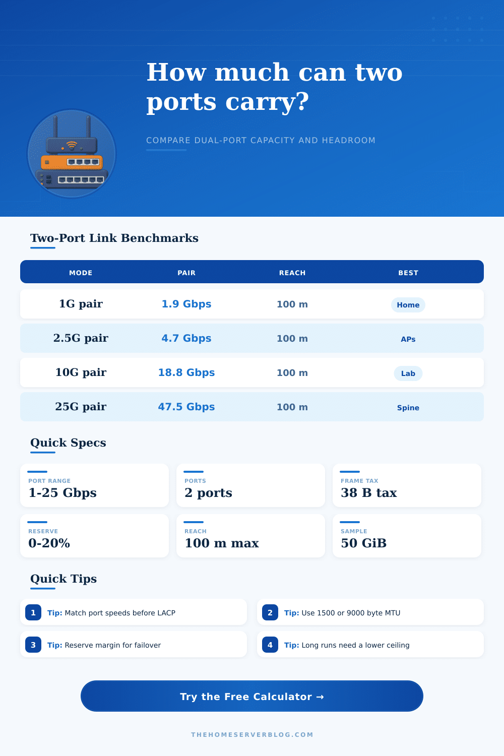
| NAS mirror | 2x10G | 18.8 Gbps | MTU |
| AP uplink | 2x2.5G | 4.7 Gbps | Airtime |
| Camera trunk | 2x1G | 1.9 Gbps | Steady load |
| HA pair | 2x10G | 9.4 Gbps | Failover |
This calculator keeps raw port speed, protocol overhead, and mode behavior separate so you can see where two-port capacity is really lost.
When connecting a NAS device to a lab switch through two 10G ports, it may appear that 20 Gbps of bandwidth will be available to the NAS device. However, two 10G ports do not necessarly offers 20 Gbps of bandwidth. Many people may assume that connecting a device to two ports will double the speed to which that device can send data through that network.
However, the actual speed at which the device will be able to transfer data will depend on how the two 10G ports are configure. If the network traffic is not even across the two 10G ports, the traffic will remain on one port only. The method in which the two 10G ports are linked will determine the total bandwidth that is available to the two ports together.
Two 10G Ports Do Not Always Give 20 Gbps
Link Aggregation Control Protocol (LACP) can distribute the traffic across the two 10G ports by using a hashing algorithm to determine to which of the two 10G ports the traffic will be sent. Using LACP can increase the bandwidth available to the devices connected to those two 10G ports. However, LACP will only increase the bandwidth if the hashing algorithm evenly distribute the network traffic across the two 10G ports.
If the hashing algorithm does not even out the data traffic across the two 10G ports, the data will remain on one port. Some setups may have one of the 10G ports configured as a standby port to take over in the case that the other 10G port should fail. In these configurations, one of the 10G ports will remain idle.
In the case of having a standby 10G port, the bandwidth will be halve because one of the ports will remain idle. Another configuration that can reduce the available bandwidth for NAS device is storage mirroring. Storage mirroring creates a duplicate set of data on the second 10G port.
Whenever data is written to the storage devices, the data must be written to the mirrored storage devices, which creates delays in the writing process. These delays will reduce the effective speed at which the storage devices can transfer data. Several technical factors can reduce the effective bandwidth that the two 10G ports on the switch to which the NAS device is connect can provide.
One of these factors is protocol overhead. Every data packet contains overhead information that takes up some of the available bandwidth. The protocol overhead for most protocols consumes approximately 6% of the available bandwidth on the 10G ports.
The other technical factor that can reduce the available bandwidth is the Maximum Transmission Unit (MTU) size for the 10G ports. The default MTU size for most networks is 1500 bytes. With the default setting, 97.5% of the available bandwidth on the data frame is used for the data payload.
Using a jumbo frame configuration will allow for a larger percentage of the data frame to be used for the data payload. When using a jumbo frame configuration, less data frames will be created that must traverse the two 10G ports. The physical and electrical characteristics of the network between the NAS device and the switch can also impact the two 10G ports.
The signal quality of data transmitted over copper cables decline with distance. The longer the cable between the two devices, the more worse the signal quality. If the length of the copper cable that connects the two devices is more than 100 meters, the signal quality will decline.
Poor signal quality can introduce error into the data that is transferred between the two devices. Another physical factor that you must consider is the speed of each 10G port. The two 10G ports must be set to the same speed.
If the two 10G ports are not set to the same speed, they will not be able to bond with each other. Finally, it is a best practice to reserve 15% to 20% of the available bandwidth on the two 10G ports for bursts in network traffic. If you do not reserve 15% to 20% of the available bandwidth for network traffic bursts, the bursts in network traffic will exceed the available headroom for the switch to handle the traffic.