VSWR Calculator
Convert forward and reflected RF power into VSWR, return loss, mismatch loss, delivered power, and feed line estimates for antenna and bench measurements.
Calculated RF Match
| VSWR | Reflection Coefficient | Reflected Power | Return Loss | Station Meaning |
|---|---|---|---|---|
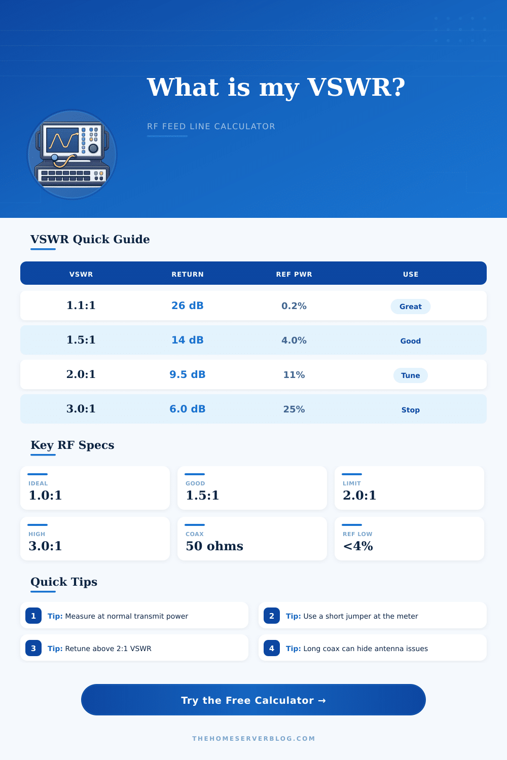
| 1.0:1 | 0.000 | 0.0% | Infinite | Perfect theoretical match |
| 1.2:1 | 0.091 | 0.8% | 20.8 dB | Excellent antenna and feed line match |
| 1.5:1 | 0.200 | 4.0% | 14.0 dB | Good for most transmitters without retuning |
| 2.0:1 | 0.333 | 11.1% | 9.5 dB | Common upper limit before foldback |
| 3.0:1 | 0.500 | 25.0% | 6.0 dB | Investigate antenna, connectors, or tuning |
| 5.0:1 | 0.667 | 44.4% | 3.5 dB | High stress; avoid full-power transmit |
| Feed Line | Loss per 100 ft | Velocity Factor | Typical Use | Practical Note |
|---|---|---|---|---|
| RG-58/U | 4.1 dB | 0.66 | Short jumpers, mobile runs | Avoid long VHF/UHF runs |
| RG-8X | 2.6 dB | 0.78 | Portable HF/VHF stations | Good balance of size and loss |
| LMR-240 | 1.9 dB | 0.84 | Compact low-loss runs | Useful for attic and mast feeds |
| RG-213/U | 1.55 dB | 0.66 | General station feed line | Rugged but larger bend radius |
| LMR-400 | 1.2 dB | 0.85 | VHF/UHF base stations | Strong choice for rooftop antennas |
| 1/2 inch hardline | 0.75 dB | 0.88 | Repeater and tower sites | Lowest loss in longer permanent runs |
| Service or Band | Typical Frequency | Common Line | Preferred VSWR | Why It Matters |
|---|---|---|---|---|
| HF amateur | 3.5 to 29.7 MHz | RG-213 or ladder line | 1.5:1 or lower | Tuners can mask mismatch but line loss still rises |
| CB radio | 27 MHz | RG-58 or RG-8X | 1.5:1 or lower | Mobile whips often need physical length trimming |
| VHF 2 meter | 144 to 148 MHz | LMR-240 or LMR-400 | 1.7:1 or lower | Coax loss becomes visible on longer mast runs |
| UHF 70 cm | 420 to 450 MHz | LMR-400 or hardline | 1.5:1 or lower | Small connector faults can create large loss |
| Wi-Fi 2.4 GHz | 2400 MHz | Microwave coax | 1.5:1 or lower | Feed line loss often dominates the link budget |
| Project | Measurement Point | Normal Inputs | Primary Result | Secondary Check |
|---|---|---|---|---|
| New VHF base antenna | Radio end before final weatherproofing | 50 W forward, 1 to 3 W reflected | VSWR near 1.4:1 to 1.7:1 | Compare after installing drip loop |
| HF dipole trim | Antenna analyzer or station wattmeter | Band center frequency and reflected power | Lowest VSWR near target frequency | Check both band edges before cutting wire |
| Repeater feed line check | After duplexer and before tower line | High duty-cycle transmitter power | Low reflected power at full carrier | Confirm cable loss and connector heating |
| Mobile CB whip | Inline meter at radio | 4 W carrier and whip adjustment | VSWR below 1.5:1 on channel 20 | Compare channels 1 and 40 for length trim |
| Microwave bench link | Directional coupler output | Low forward power and short coax | Return loss above 14 dB | Use adapters rated for frequency |
Formulas use reflection coefficient = square root of reflected power divided by forward power, VSWR = (1 + coefficient) / (1 - coefficient), return loss = -20 log10(coefficient), and mismatch loss = -10 log10(1 - coefficient squared). Feed line loss is an estimate based on reference attenuation and frequency scaling.
Voltage Standing Wave Ratio, or VSWR, is a measurement of how well the transmitter, the feed line, and the antenna work together. When the transmitter, the feed line, and the antenna is all correctly matched, the power from the transmitter will exit the antenna and travel outward into air as radio signals. If the three component are not properly matched to one another, though, the power will reflect off from the antenna and feed line back towards the transmitter.
This reflected power create what is known as a standing wave. High VSWR ratings can create heat within the radio hardware, which can eventualy lead to damage to those hardware component. While many people may believe that high VSWR ratings impact the quality of the signal that the antenna emits, high VSWR ratings also pose a risk to the hardware of the radio transmission system.
What Is VSWR and How It Affects Radios
VSWR can be calculated using a calculator that requires the power of the transmitter’s signal that is reflected off at the antenna and the power of the signal that the transmitter transmits. The ratio of those two value creates the VSWR rating for that transmitter. A perfect VSWR ratio is 1.0:1.
A perfect VSWR is a theoretical value, though, that is idealy difficult to achieve with any radio transmitter. A VSWR of 1.5:1 or less is considered to be an efficient radio signal system. A VSWR that is below 1.5:1 indicate that the radio signals are being safely transmitted.
The location at which you measure VSWR is important to understanding the signal strength of a radio signal. If you measure the VSWR at the radio signal transmitter, for instance, the measurement will account for the signal loss of any feed line that lies between the radio and the antenna. Because a long or lossy feed line will absorb some of the power of the reflected signal, a long or lossy feed line can make it appear as if a radio antenna has a high VSWR ratio despite the true VSWR of that antenna.
To measure the VSWR of an antenna, then, it is important to measure as close to the antenna as possible. If it is not possible to measure the VSWR of the signal at the antenna, though, another tool can be used to estimate how strong the signal is after it pass through the feed line. The type of feed line that people use to transmit signals from the radio to the antenna is also important to consider when using radio signals.
Different frequency require different types of feed lines. For instance, a feed line that is appropriate for transmitting a signal at 27 MHz may not be appropriate for a signal at 2.4 GHz. As the frequency of the signal increases, the loss per foot of the feed line increase.
Additionally, the impact of any poor connector along the feed line becomes more pronounced at higher signal frequencies. Even a small kink in a feed line can reflect a signal at high frequencies, leading to the apparent failure of the antenna. Another measurement of the health of a signal is called return loss.
Return loss help to indicate how many decibels of power the antenna reflects. A high value of return loss is a positive indicator of the health of the radio system. High return loss ratings indicate that most of the power that the transmitter emits reaches the antenna and does not reflect back to the transmitter.
If the power that is delivered to the antenna is significantly less than the forward power of the radio signal, the signal is being lost to heat within the feed line. If the VSWR ratio of a radio signal is higher than 2.0:1, it is recommended that the signal stop being use by the transmitter. If the VSWR ratio is higher than 1.5:1, the antenna may need to be physically adjusted.
Additionally, if the VSWR ratio of a signal is high, the transmitter may have foldback circuitry. Foldback circuitry is a system that reduces the power of the signal when the VSWR ratio is high. This system protect the transmitter hardware, but at the cost of the range of the radio signal.
Tuning is used to adjust the antenna or feed line so that the VSWR ratio of the signal is lower. The goal in tuning is to allow the radio signals to travel forward out of the antenna rather than reflecting back towards the transmitter.