Wireless Access Point Coverage Calculator
Estimate access point count, usable WiFi cell size, client capacity, channel pressure, and recommended overlap for a home, office, or lab network.
Wireless Access Point Plan
| AP Class | Good 5 GHz Cell | Practical Clients | Best Use |
|---|---|---|---|
| WiFi 5 AC1200 | 700-900 sq ft | 30-45 | Light home or guest coverage |
| WiFi 6 AX1800 | 800-1100 sq ft | 45-65 | Home office and normal roaming |
| WiFi 6 Pro | 900-1300 sq ft | 65-95 | Dense rooms and faster clients |
| WiFi 6E / WiFi 7 | 600-1000 sq ft | 70-120 | Clean 6 GHz cells and high throughput |
| Target RSSI | Planning Goal | Roaming Notes | Typical Result |
|---|---|---|---|
| -72 dBm | Basic data / IoT | Can roam late | Largest cells |
| -70 dBm | Web and email | Acceptable for light use | Moderate cells |
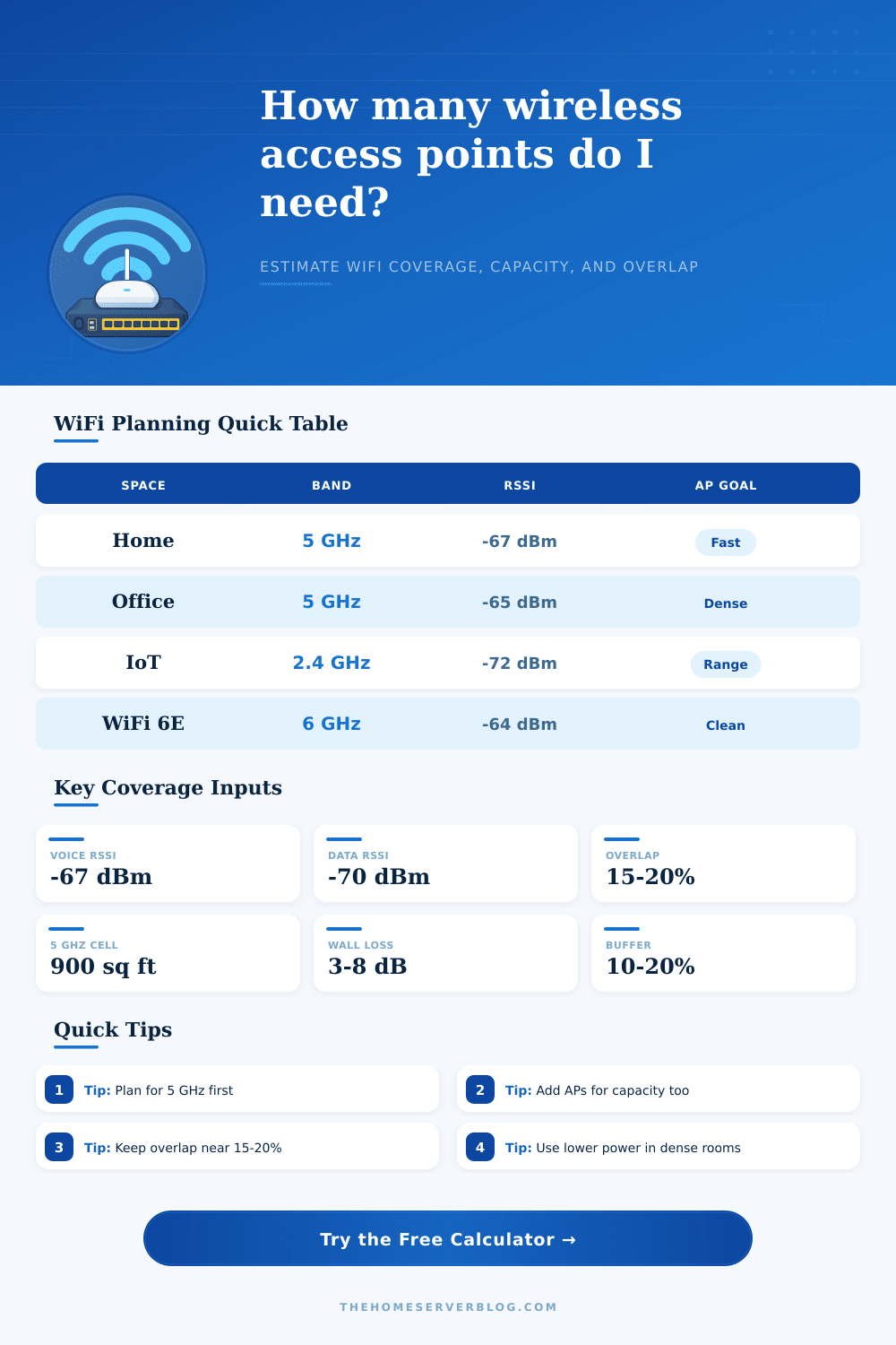
| -67 dBm | Voice and video | Common design target | Good roaming |
| -65 dBm | Dense office | Better airtime efficiency | Smaller cells |
| -60 dBm | High performance | Needs careful power tuning | Many APs |
| Band / Width | Non-Overlapping Plan | Range Behavior | Practical Limit |
|---|---|---|---|
| 2.4 GHz / 20 MHz | Channels 1, 6, 11 | Longest range | Congestion and IoT load |
| 5 GHz / 40 MHz | Good reuse in homes | Balanced range | DFS awareness needed |
| 5 GHz / 80 MHz | Fewer clean channels | Shorter reliable edge | Best for low AP counts |
| 6 GHz / 80 MHz | Many clean channels | Lower wall penetration | Needs WiFi 6E or newer |
| Project Type | Example Size | Common AP Count | Design Driver |
|---|---|---|---|
| Apartment | 700-1200 sq ft | 1 AP | Placement and interference |
| Two-story home | 1800-3200 sq ft | 2-4 APs | Floors and roaming overlap |
| Home lab office | 1200-2500 sq ft | 2-3 APs | Video calls and wired backhaul |
| Small office | 2500-6000 sq ft | 4-8 APs | Client density and airtime |
A wireless network rely on the placement of wireless access points. The placement of these access points will determine the function of the network itself. Many individuals may want to improve the function of a wireless network by purchasing a single, more powerful router.
However, using a single, powerful router can be ineffective in many instance because a single router cant overcome all of the obstacles that may impede the wireless signal. A wireless network does not function according to the strength or loud of the signal that the router emits. Instead, the function of the wireless network relates to how clear the devices can communicate with the access point.
How to Place WiFi Access Points for Best Coverage and Speed
Therefore, the individual must map out the wireless network to ensure that the areas of the building that the network is to be covered by have an appropriate amount of overlap with the signals from the access points. One of the main factors that will influence the function of the network is the physical structure of the building itself. The materials that is used to construct a building may impact the strength of the signal that the access points emit.
For instance, wireless signals can travel through drywall relatively easy, but can struggle to travel through materials like concrete, tile, or metal backed insulation. These type of construction materials will absorb some of the radio frequencies that the access points emit, and the absorption of those signals will reduce the strength of the wireless signal. Therefore, if a building contains many of these type of materials, it is usually an incorrect choice to use a single access point for that building.
Instead, the use of multiple smaller access points will allow for the signals to travel shorter distances through these construction materials, which will increase the speed of the wireless network. Wireless networks can use different frequency bands to emit their signals. The 2.4 GHz frequency band can travel long distances and can penetrate walls, but its slow data transmission rate and high chance of interference with other wireless networks limit its usefulness for many applications.
The 2.4 GHz band is best used for devices that do not require high data transmission rates, such as smart thermostats or smart lightbulbs. The 5 GHz and 6 GHz bands, however, allow for faster data transmission rates. The benefit of using the 5 GHz and 6 GHz bands is that they do not experience as many interference from other wireless devices.
The drawback to using these bands is that their signals do not travel as far then the 2.4 GHz signal. Thus, if a network is designed with the range of the 2.4 GHz signal in mind alone, devices that require high data transmission rates will experience slow speeds due to the shorter range of the 5 GHz and 6 GHz signals. Another factor to consider is the capacity of the network.
While range relates to the number of devices that can be in range of the signal, capacity is the ability of the network to support many of those devices at once. Thus, a device may experience a strong signal, but if many of the devices in the same area is using the network, those devices may experience slow speeds. Each access point have a limit to the number of devices that can use the network at any given time.
If the number of devices that are using the network is beyond the limit of that access point, the throughput of that network will decrease. Therefore, an access point may be designed with a certain number of user in mind. Consequently, if there are many users of the network, the number of access points that is implemented into the network will have to be decided based off the number of users.
Thus, coverage ensure that the signal is present in each location, but capacity ensures that the signal is strong enough to be used by many devices. The roaming process is the process in which a mobile device move from one access point to another. In order to establish roaming between devices, there must be an overlap of the signals of those access points.
An overlap of 15 to 20 percent between access points is recommended. If there is too small of an overlap between access points, there may be “dead zones” in which no signal is recieve. If there is too large of an overlap between access points, the devices may not be able to find the shortest route to the access point.
An overlap calculator can be used to calculate the baseline signal strength of the access points. Based on that baseline, the transmit power of each access point can be reduced to allow the devices to roam from one access point to the next. Additionally, the reduction of the transmit power of the access points will reduce the amount that the access points interfere with one another.