HomeServerBlog wireless backhaul planner
Wireless Backhaul Capacity Calculator
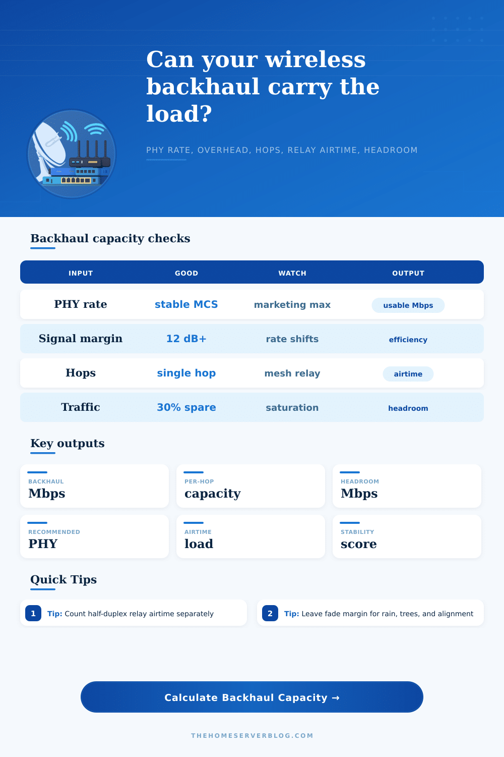
Estimate real backhaul capacity after protocol overhead, signal margin, channel width behavior, MIMO stream stability, fade reserve, hop count, and half-duplex relay airtime.
1Backhaul presets
2Radio and traffic inputs
Capacity breakdown
Planning verdict
3Live capacity labels
4Backhaul technology grid
5 GHz PtP
150-700 Mbps usableGood for rural and rooftop bridges when spectrum is clean and antennas are directional.6 GHz / Wi-Fi 6E
400-1600 Mbps usableCleaner channels and wider bandwidth help, but DFS-like planning and client ecosystem still matter.60 GHz
1-3 Gbps short rangeExcellent for rooftops and line-of-sight hops; rain fade and aiming reserve are not optional.Outdoor mesh
Relay-limitedEach half-duplex retransmission consumes airtime, so a two-hop path can feel smaller than the radio PHY implies.WISP CPE
Plan to SLASector load, airtime fairness, and uplink ratios often matter more than one subscriber radio PHY.LTE/5G bridge
Variable reserveUse conservative PHY and high fade reserve because cellular scheduler load changes by hour and location.5Reference tables
| Signal margin | Capacity factor | Meaning | Planning action |
|---|---|---|---|
| 0-2 dB | 55% | Rate shifts, retries, and outages are likely. | Lower MCS, improve alignment, or choose narrower channel. |
| 3-5 dB | 72% | Usable but fragile during noise or rain events. | Add fade reserve before promising client throughput. |
| 6-9 dB | 88% | Moderate stability for everyday traffic. | Watch retry counters and peak-hour modulation. |
| 10-14 dB | 96% | Stable for most outdoor Wi-Fi links. | Good target for camera, barn, and CPE links. |
| 15+ dB | 100% | Strong margin for high MCS operation. | Consider wider channel only if spectrum is clean. |
| Channel width | Stability factor | Best use | Capacity warning |
|---|---|---|---|
| 20 MHz | 94% | Long rural links, noisy bands, WISP sectors. | Lower peak PHY but often better consistency. |
| 40 MHz | 100% | Balanced outdoor Wi-Fi backhaul. | Usually the clean planning baseline. |
| 80 MHz | 96% | Short, clean PtP and Wi-Fi 6 backhaul. | Can suffer from more interference exposure. |
| 160 MHz | 90% | 6 GHz or controlled rooftop links. | Needs clean spectrum and stable client support. |
| 320 MHz | 84% | Wi-Fi 7 style lab or very clean backhaul. | High headline PHY can hide poor usable airtime. |
| 2160 MHz / 60 GHz | 88% | Short line-of-sight rooftop links. | Keep rain fade and aiming reserve high. |
| Path design | Airtime divisor model | What it means | Common fix |
|---|---|---|---|
| Single PtP hop | 1 hop + 0 relays = 1x | Most of the usable radio capacity remains available end to end. | Use directional antennas and clean channel planning. |
| Two-hop mesh | 2 hops + 1 relay = 3x | Shared-airtime retransmission can cut apparent capacity sharply. | Use wired backhaul, tri-band mesh, or separate relay channel. |
| Camera chain | 2-4 hops plus relay count | Many small streams can still saturate management and ACK airtime. | Cap camera bitrate and avoid daisy-chain topology. |
| WISP subscriber | Hop count plus sector contention | The CPE link may be fine while shared sector airtime is not. | Budget sector oversubscription separately from this link. |
| Headroom band | Status | Interpretation | Recommended action |
|---|---|---|---|
| 30%+ spare | Ready | Enough room for bursts, retries, and client growth. | Monitor signal margin and retry rate monthly. |
| 10-29% spare | Watch | Works, but congestion can appear during peak load or weather. | Reduce overhead, narrow the channel, or upgrade antennas. |
| 0-9% spare | Tight | Small RF changes can cause buffering or packet loss. | Raise PHY, add a wired segment, or reduce client traffic. |
| Negative headroom | Overloaded | Requested client traffic exceeds modeled backhaul capacity. | Upgrade radio, split traffic, or remove half-duplex relay airtime. |
6Backhaul planning tips
On the radio interface, I see a PHY rate of 1.2 gigabits per second. This sounds like a lot, but it’s actualy just the speed of the pipe before friction and leaks eat into your real throughput. But it’s not really that big. That’s your speed before distance and interference take their toll on your real-world throughput.
Using marketing headlines instead of usable capacity are how wireless backhaul plans go wrong. That gap determines whether connection works or not. But the calculator eliminate all that and does the math for you to find out how much data link can carry in real conditions. You don’t need to push a button, but understanding why it removes those things is more important.
Why Real Speed Is Slower Than Advertised
The first one that slow things down is called protocol overhead. All Wi-Fi transmissions include management frames, acknowledgements, and encryption headers that don’t move user data, but still use up airtime. Before any customer traffic flow on a typical link, nearly forty percent of the theoretical throughput will have been spent on these necessities. It’s not a bug; it’s how the protocol prevents packets from getting lost.
There is another level of complexity: how stable is your signal? Maybe you got lucky with a clear line of sight right now, but over time your signal will weaken as trees grows, rain falls, humidity increases, etc. There’s a reason the tool has a margin reserve; if you use max theoretical throughput, you’ll be down when it rains. If you’re below 10 decibel signal margin, then you’re probably close to being at the edge of the radios’ abilities to maintain the link. That’s where people mess up. They optimize for top speed during install, but networks isn’t supposed to run in perfect conditions. They need to survive rain, bad weather, interference and more.
Performance is also related to the geometry of the path. Point-to-point retains a large percentage of its bandwidth. Adding a relay create half-duplex penalties. The relay must wait and listen before it speaks, which effectively halves available bandwidth on that segment. Compound that with multiple relays in a meshed outdoor network and airtime consumption compounds rapidly. Slices of the shared spectrum is taken off by each hop, reducing amount of the overall band available for actual data. This can be seen quite clearly from reference table. A two-hop path is effectively smaller then the radio spec would make you believe, since they’re spending time coordinating instead of actually transmitting.
Likewise, the best choice for channel width are a balance. The wider your channels, the greater their peak rate, but the more spectrum you expose to interference and other noise. You can run in a hundred sixty megahertz wide channel, or an eighty megahertz channel, if you’ve got a nice clean rooftop environment. If you’re in a city with lots of neighbors running next door networks on overlapping frequency ranges, however, it’s not uncommon to see much better real world consistency by dialing that back to a forty megahertz wide channel. This keeps your signal-to-noise ratio up. It’s not so much a question of having the largest pipe as having a clean one.
This refers to the final output headroom, which is where we’re checking if your design has some breathing room. Ideally a good backhaul should of had at least 30%+ excess. This allows for bursty traffic, firmware updates, and unexpected client growth without compromising air time. Tight margins on the calculator indicate your existing configuration are fragile. Not that something’s wrong with the gear, just that the physics of your environment are fighting for the same bandwidth as what you need.
When planning your wireless network, it’s time to stop focusing on headline numbers and start focusing on long-term efficiency. You don’t need a link that chokes during installation testing. Instead, you want one that will be there when the office gets busy, when the weather turns, or when a client asks why they can’t download a video file. Build in fade reserves, overhead and relay penalties up front and create networks that can stand up to real life. Never aim for maximum speed on a perfect day. Aim instead for reliable performance on the worst day of the year.