HomeServerBlog wireless path planner
Antenna Height for Line of Sight Calculator
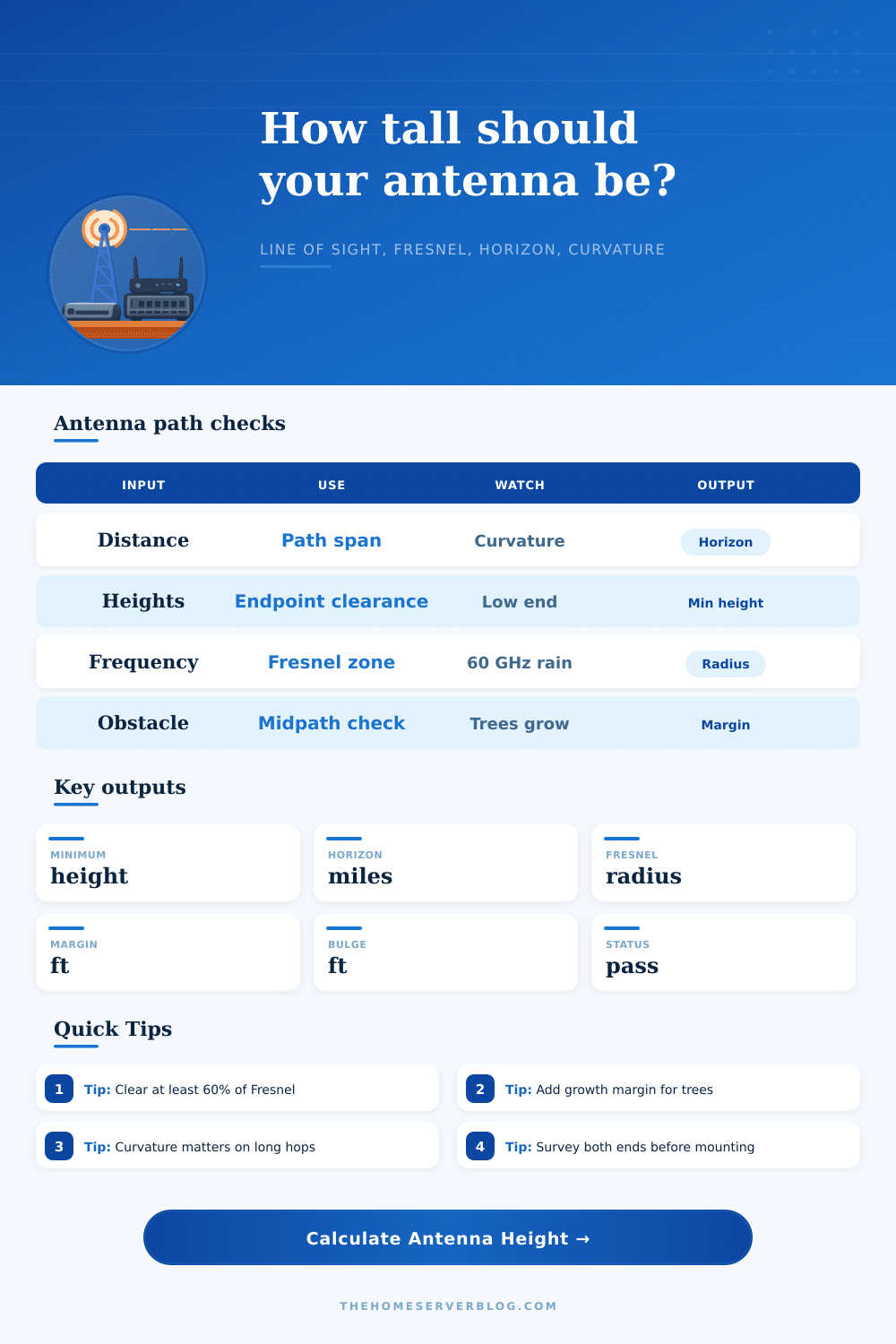
Estimate the antenna height needed for a clear point-to-point path, including radio horizon, earth curvature, mid-path obstacle height, terrain bulge allowance, and the Fresnel clearance your link actually needs.
1Link presets
2Antenna path inputs
Path breakdown
Clearance status
3Useful labels
4Antenna frequency comparison grid
5Tables
| Current path item | Formula logic | Value | Planning note |
|---|
| Band | Typical use | Fresnel behavior | Height takeaway |
|---|---|---|---|
| 900 MHz | Rural telemetry, long camera hops | Largest Fresnel zone | Often needs more vertical clearance than the radio range suggests. |
| 2.4 GHz | Farm Wi-Fi bridge, older mesh | Broad Fresnel zone | Forgiving foliage loss is limited; keep the zone open. |
| 5 GHz | Rooftop and WISP CPE links | Moderate Fresnel zone | Good balance for home lab and rural backhaul paths. |
| 6 GHz | Wi-Fi 6E/7 short outdoor links | Slightly tighter zone than 5 GHz | Cleaner spectrum helps only when the visual path is clean. |
| 24 GHz | Short fixed wireless hops | Small Fresnel zone | Precise aiming and weather margin become more important. |
| 60 GHz | Short high-capacity rooftop hop | Very small Fresnel zone | Height may be modest, but rain fade and obstruction tolerance are strict. |
| Preset | Distance | Frequency | Design intent |
|---|---|---|---|
| Farm Wi-Fi Bridge | 1.2 mi | 5.8 GHz | House to outbuilding with a moderate tree line. |
| Rooftop 5GHz Link | 2.5 mi | 5.2 GHz | Urban roof-to-roof link with parapet and chimney allowance. |
| 60GHz Short Hop | 0.25 mi | 60 GHz | Clean, short, high-throughput hop with tight Fresnel zone. |
| Rural Camera Backhaul | 3.8 mi | 5.8 GHz | Remote camera path with trees and ridge allowance. |
| Barn to House Link | 0.6 mi | 2.4 GHz | Lower-frequency farm path with larger Fresnel clearance need. |
| Hilltop Relay | 6.5 mi | 5.8 GHz | Longer hop where curvature and endpoint height dominate. |
| Lake Crossing Link | 4.2 mi | 5.8 GHz | Flat-water path with strong curvature and reflection awareness. |
| Neighborhood Mesh | 0.9 mi | 6 GHz | Short roof mesh path with modest obstacle clearance. |
| WISP CPE Path | 5.1 mi | 5.8 GHz | Customer-prem radio toward a provider sector or relay. |
| Clearance result | Margin band | Action | Field check |
|---|---|---|---|
| Comfortable pass | 10 ft or more | Document mount height and final aim. | Confirm both antennas still clear after seasonal growth. |
| Usable but tight | 0 to 10 ft | Raise the lower end or reduce obstacle uncertainty. | Check trees, roof ridges, and pole sway. |
| Fresnel clipped | Negative margin | Add mast height, move one endpoint, or use an intermediate relay. | Do not trust visual line of sight alone. |
| Horizon limited | Distance beyond horizon | Raise one or both endpoints before tuning radio settings. | Long water and flat terrain paths need conservative surveys. |
6Tips
This calculator is a planning estimate for antenna placement. Final outdoor links should be confirmed with a path survey, local mounting rules, safe mast hardware, lightning protection, and the radio vendor's installation guidance.
“Look,” you say as you hold out a wireless bridge in one hand and stand on the roof, looking across the half-mile at the barn. “Through the trees, I can see the path.” So you mount the antenna, turn it on, and behold: Nothing. No signal strength whatsoever. This is classic visual line of sight problem.
Yes, sight is different. Your eyes pick up light waves bouncing around obstacles. However, radio waves require an invisible wider corridor to get anywhere effectivly. It’s called the Fresnel zone, and if you don’t pay attention to it, you’ll kill your connection throughput.
Why Your Eyes Can Be Wrong About Wireless Signals
That’s because hardware is typically not the problem; the problem is shape of the ground; specifically the way the planet curves under your signal, such that the bulge can be unnoticeable at short range, but become substantial out to three or four miles. And simple straight line between two antennas will often cut directly across a stand of oak trees, or even a ridge, that you’d never imagined might matter much.
That’s where the calculator up top comes in: Instead of these general concerns about heights, it actualy runs the numbers for you. And it considers the curvature of the earth. It uses a standard refraction coefficient, which models radio waves bending just a bit back down to surface. That 4/3 earth radius model projects your real radio horizon beyond your visual one…but it also makes the ground bulge outward more than you would of thought, halfway along the line.
When you understand what’s going into this, suddenly, you see how to read the site survey different, in that it doesn’t measure a straight line when you put in antenna heights and distance. It’s calculating the mid-point sag due to curvature and gravity, and then it’s overlaying the Fresnel zone radius, which is highly dependent on frequency.
With higher frequencies such as 60 GHz, the Fresnel zone is very small, and it fits nicely through branches. But they must be perfectly aligned and can be weakened by rain. At 4 or 5 GHz, the Fresnel zones is much bigger, and require large clearances. A millimeter wave hop might only need a couple of feet of clearance vertically, whereas a 5 GHz link could take ten feet.
The calculator does all those trade-offs for you, because it displays if your proposed mast height will clear X percent of that otherwise-invisible oval. Visual line of sight isn’t good enough. Sometimes things look totally fine from your perspective, even when binoculars show an obstruction like a roof edge or tree branch clipping the first Fresnel zone. That obstruction will kill roughly half of your throughput.
The tool spits out a clearance margin number to tell you just how much breathing room remains. Subtract that number from zero. If it’s negative, you’ll experience latency spikes and packet loss. If it’s positive but small, you might get by for now, but seasonally growing things may choke the link in six months time once they leaf out.
The spreadsheets do not account for other aspects. Poles bend in windy conditions, brackets flex under heavy outdoor antenna, and snow accumulates on dish faces (which affects actual height by inches… But that can mean a lot when your margin of error is down into single digits). A couple of added feet on the lowest antenna tends to be less expensive than chasing down a marginal link due to vegetation growth and/or construction error, which is insurance.
How you choose frequency determines your height strategy too, hence the reference table on the page showing the behavior of each band. Some (like 900 MHz) bend nicely around objects but need huge vertical clearance to fit their Fresnel zone. Others (like 60 GHz) act like lasers, needing accurate pointing and getting messed up if one branch gets in the way. You have to balance what’s available in your locality against physical constraints.
In the end, constructing a solid wireless connection has as much to do with paying attention to the numbers rather than your eyes. You have to let the physics of propagation work for you by knowing when drilling a hole or raising a mast is a waste of time. The numbers will let you know if the route are viable first. The correct height up front will save hours of gnashing of teeth later, and when you see the full throughput bars and that happy little green status indicator, it won’t be magic. It’ll simply be good geometry doing exactly what it’s designed to do.