Yagi Antenna Gain Calculator
Estimate realized gain, beamwidth, front-to-back ratio, and far-field distance for classic and high-directivity UHF bridge beam builds.
Full Breakdown
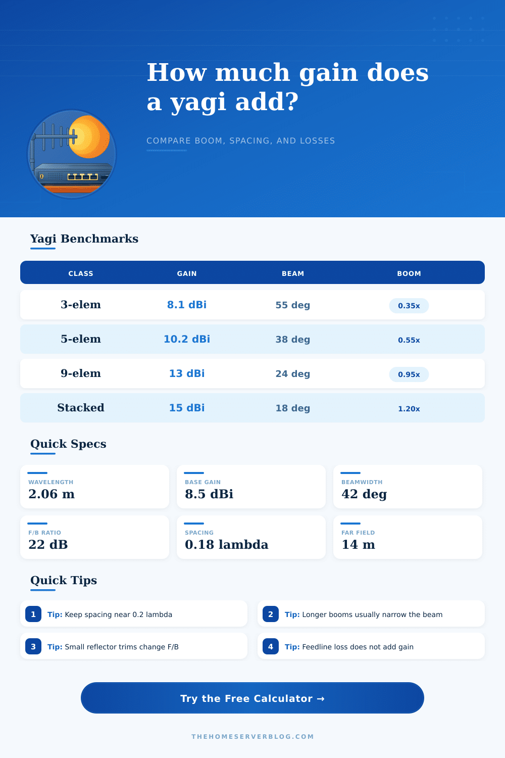
| Class | Gain | Beam | Boom |
|---|---|---|---|
| Classic 3 | 7-9 dBi | 50-65 deg | 0.3-0.4 λ |
| Mid 5 | 9-11 dBi | 35-45 deg | 0.5-0.7 λ |
| Long 9 | 12-14 dBi | 20-30 deg | 0.8-1.0 λ |
| Contest stack | 14-16 dBi | 15-22 deg | 1.1-1.4 λ |
| Band | Wavelength | Common antenna | Typical fit |
|---|---|---|---|
| 433 MHz | 69 cm | Collinear | Garage links |
| 900 MHz | 33 cm | UHF bridge beam | Rural telemetry |
| 2.4 GHz | 12.5 cm | Compact portable | Mesh backhaul |
| 5.8 GHz | 5.2 cm | Long-boom 9-element | Bridge links |
| Loss input | Typical range | Effect | Note |
|---|---|---|---|
| Taper loss | 0.5-2 dB | Lowers gain | Tames sidelobes |
| Feedline loss | 0.2-3 dB | Direct subtraction | Coax and pigtails |
| Pol mismatch | 0-3 dB | Cross-pol penalty | Check rotation |
| Pointing error | 0-5 dB | Depends on beam | Narrow beams hurt |
| Preset | Type | Gain goal | Beam goal |
|---|---|---|---|
| 2.4 GHz rooftop | Compact portable | 14 dBi | 30 deg |
| 5.8 GHz bridge | Long-boom 9-element | 29 dBi | 5 deg |
| 900 MHz yagi | UHF bridge beam | 11 dBi | 45 deg |
| High-directivity contest | Contest stack | 17 dBi | 20 deg |
Realized gain is the modeled antenna gain after efficiency, taper, feedline, polarization, and pointing losses are applied to the same geometry.
A Yagi antenna are a directional antenna that focus the radio signals in a specific direction. Many users installs a Yagi antenna on a rooftop to take advantage of the higher position that will give users a more better signal. A person may use a Yagi antenna to connect two property that are located across a valley.
However, there are various environmental factors that will affect the performance of a Yagi antenna, such as wind sway and heat in the coaxial cable that connect the antenna to the radio transmitter and receiver. Additionally, the antenna may misalign from various mounting issues. The gain of a Yagi antenna is determine by the geometry of the antenna.
How Yagi Antennas Work and What Affects Their Signal
By making the boom of the Yagi antenna longer, a person can include more director element. The more director elements included in the antenna will result in a beam of radio signals that is more focused, thus, increasing the dBi gain of the antenna. However, a person must understand that the higher the dBi gain of the antenna is, the more precise aiming the antenna’s signals.
The element count of the antenna and the boom length determine the radiation pattern of the antenna. However, the gain of a Yagi antenna is usually less than the theoretical gain due to signal losses. The distance between the antenna elements are another factor that will affect the performance of the antenna.
For Yagi antennas, the spacing between elements is usually around 0.2 wavelength. By shortening the element spacing of the antenna, a person can make it easier to mount the antenna. The real-world measurement of the performance of a Yagi antenna can be different than the theoretical model.
The reason for such a difference are due to various losses in performance of the antenna. For instance, the modeled gain of a Yagi antenna may be 14 dBi, but the actual gain is 10 dBi due to feedline losses. Using long or stiff coaxial cable, such as RG-8, to connect the antenna to the radio transmitter and receiver causes feedline losses.
Another loss in the performance of the antenna is taper loss. This loss occur when the edge elements of the antenna are softened to reduce the sidelobes that radiate from the antenna. By tapering the edge elements of a Yagi antenna, the radiation pattern of the antenna becomes smoothly.
However, taper loss also reduces the peak gain of the antenna by one or two dB. Another loss in the performance of a Yagi antenna is polarization skew. This skewing of the polarization of the antenna’s signal occur when the antenna is mismatched with the transmitting radio transmitter and receiver or when the antennas mount is twisted.
Additionally, another problem in the performance of a Yagi antenna is pointing error. A Yagi antenna has a narrow beamwidth. Thus, there is a high chance that the signal strength will dramatically drop if the antenna’s beam is pointing in the wrong direction.
The efficiency of a Yagi antenna is one measure of the performance of the antenna. The metal used to construct the antenna, the impedance of the antenna elements, and the spillover of the signal determine the efficiency of a Yagi antenna. A Yagi antenna constructed of aluminum tubing will have a higher efficiency of around 70 percent than a Yagi antenna constructed of wire elements that may corrode over time.
Another measurement of the performance of a Yagi antenna is the front-to-back ratio of the antenna. This measurement determines how much signal the antenna will reject from the rear of the antenna. Using the front-to-back ratio measurement, a person can tune the reflector of the antenna to maximize signal rejection from the rear of the antenna.
The beamwidth of a Yagi antenna is another measurement of the performance of the antenna. The beamwidth of the antenna determine in what way the person will use the Yagi antenna. For example, a beamwidth of 50 degrees may be acceptable for various scanning application.
However, a beamwidth of 20 degrees will require a rotator to move the antenna to various directions because it is very difficultly to manually point the antenna with such a narrow beamwidth. The distance at which the Yagi antennas signal will stabilize in measurement is referred to as the far-field distance. If a person measures the Yagi antenna too close to the antenna, the measurements will not be accurate.
The various losses in the performance of a Yagi antenna will change the expected performance of the antenna. A person will have to account for these loss when planning to build or use a Yagi antenna. For instance, the feedline penalty directly affects the performance of the antenna.
Every dB of attenuation in the coaxial cable that connects the antenna to the radio transmitter and receiver is a dB less of signal reaching the antenna’s element. Thus, a person will want to minimize the length of the coaxial cable used to connect the Yagi antenna. Finally, a person will have to calculate the realized numbers of a Yagi antenna by consulting the technical specification of the antenna to determine how to construct the antenna to meet the expectations of the antennas users.
You should of checked the spesifications first.