Satellite Antenna Gain Calculator
Estimate dish gain, beamwidth, effective aperture, and EIRP for receive and transmit satellite links.
Full Breakdown
| Band | Range | Wavelength | Typical use |
|---|---|---|---|
| C downlink | 3.7-4.2 GHz | 7.5-8.1 cm | Rain tolerant receive links |
| C uplink | 5.925-6.425 GHz | 4.7-5.1 cm | Earth station uplinks |
| Ku band | 10.7-12.75 GHz | 2.4-2.8 cm | TV and VSAT terminals |
| Ka band | 17.7-31.0 GHz | 1.0-1.7 cm | High throughput gateways |
| Dish size | Gain @12 GHz | Beamwidth | Common use |
|---|---|---|---|
| 45 cm | 33.2 dBi | 4.4 deg | Portable Ku receive |
| 60 cm | 35.7 dBi | 3.3 deg | Home TV and light VSAT |
| 90 cm | 38.3 dBi | 2.2 deg | Stronger Ku or C receive |
| 1.2 m | 41.6 dBi | 1.6 deg | Earth station and hub links |
| Loss source | Typical dB | Good practice | Why it matters |
|---|---|---|---|
| Feed network | 0.3-0.8 | Keep run short | Reduces usable drive power |
| Radome | 0.1-0.5 | Use low-loss cover | Ka bands are sensitive |
| Pointing | 0.2-1.5 | Align carefully | Small beams miss fast |
| Polarization | 0.1-0.4 | Check skew | Cross-pol rejection matters |
| Scenario | Band | Dish size | What to watch |
|---|---|---|---|
| TV receive dish | Ku downlink | 45-60 cm | Rain fade and roof view |
| VSAT uplink | Ku uplink | 75 cm-1.2 m | BUC power and alignment |
| Gateway earth station | Ka uplink | 1.2-2.4 m | Pointing and radome loss |
| C-band hub | C uplink | 3.7-4.5 m | Feed support and wind load |
This calculator keeps reflector gain, aperture size, and loss budget separate so you can see where the final link number really comes from.
Antenna gain measure how effectively a satellite dish turn electrical signal into radio wave. Antenna gain also measure the dish’s ability to capture radio waves from the sky and turn them into data. The concept of antenna gain are important to understand in that antenna gain determine the strength of the signal from the satellite.
If the antenna gain are too low, the signal from the satellite will flicker or drop off altogether. If the antenna gain is insufficient, the satellite link will fail. The amount of antenna gain come from the size of the satellite dish, the frequency of the signal, and the physical properties of the satellite dish antenna.
How Antenna Gain Affects Satellite Signals
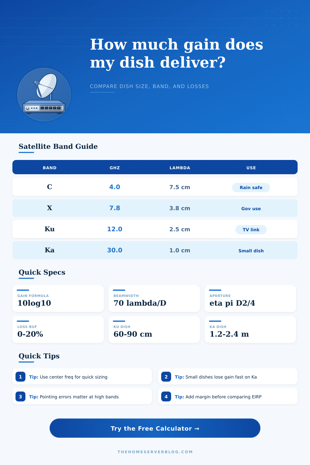
The larger the satellite dish, the more antenna gain the dish will create. Additionally, the frequency of the signal will also have an effect on the gain of the antenna. For instance, C-band frequency move at 4 GHz, creating wavelength of 7.5 centimeters.
Ka-band frequencies move at 30 GHz, creating wavelength of 1 centimeter. Therefore, Ka-band require more precision in its satellite dishes than C-band. Because Ka-band require such high precision with its dishes, dishes of relatively small size are used for Ku-band television signals.
Conversely, large dish, such as meter-class dishes are used at the gateways. The actual antenna gain for a dish will always be less than the theoretical antenna gain for the dish. Many satellite dish are only around 60 to 70 percent efficient in their functions.
The reason for this is that prime-focus dishes tend to suffer from signal spillover. Additionally, the hardware that make up the satellite dish, such as the feed horns can lose around 0.5 dB of signal strength. A half-degree misalignment between the dish and the satellite can cause pointing error of as little as 1 dB.
Dishes are also often enclosed in radomes to protect the antenna from the weather, which also cause signal losses. Signal strength can also be lost due to polarization skew. To account for these losses in the satellite dish, margins must be plan into the system.
If the calculation of antenna gain includes margins, the gross antenna gain will decrease to a net antenna gain. For uplink signals, the antenna gain must be combined with the power of the BUC to calculate the Effective Isotropic Radiated Power (EIRP) of the signal. The satellite measure the EIRP, which is the value of the uplink signal.
The beamwidth of a satellite dish is relate to its antenna gain and alignment. A 60 cm Ku-band dish at 12 GHz will have a beamwidth of 3 degrees. This beamwidth is relatively forgiving in misalignment of the dish for home use.
A 2.4 meter Ka-band dish will have a beamwidth of less than 1 degree. Therefore, such a dish will be very sensitive to movement caused by the wind. Such a narrow beamwidth can cause the signal to fail if the dish shift in position by even the smallest of amounts.
Both different size of dishes can exhibit the differences between the gains and beamwidths of those different types of dishes. One of the mistake that a person can make when setting up a satellite dish is ignoring the impact that frequency shift will have on antenna gain. For instance, the uplink signal at Ku-band frequencies at 14 GHz will require more antenna gain than the downlink receive signal at the same frequency.
However, a person may mistakenly think that the same size of dish will perform equally for these two type of signals. The 0.3 dB pointing error is more significant for Ka-band frequencies than for other bands. Additionally, a margin must be used to account for unknown issues to the system.
Overall, if the antenna gain and the margin are calculate correctly, a person will be able to engineer a stable link to the satellite.