HomeServerBlog 5G NR planning tool
5G Numerology Calculator
Estimate 5G NR subcarrier spacing, slot duration, symbols per radio frame, resource block bandwidth, TDD downlink and uplink symbol budgets, mini-slot timing, and whether a numerology plan fits a latency target.
📶5G deployment presets
⚙Numerology and carrier inputs
Calculation breakdown
Planning status
📊Slot, SCS, RB, and latency cards
Frame-level scheduling granularity from the selected numerology.
Duration of the selected 2, 4, or 7 symbol mini-slot.
RB bandwidth divided by the configured RF carrier bandwidth.
Estimated uplink symbols available in one 10 ms radio frame.
🗂Numerology comparison grid
📚5G NR reference tables
| Numerology | Subcarrier spacing | Normal slot duration | Common planning use |
|---|---|---|---|
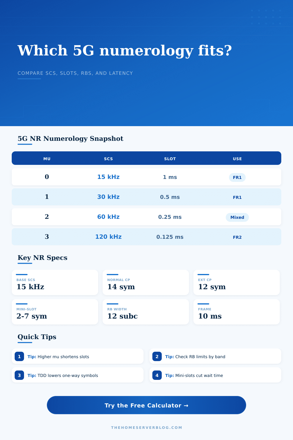
| mu 0 | 15 kHz | 1.000 ms | FR1 coverage layers, DSS-style planning, and lower-band channels. |
| mu 1 | 30 kHz | 0.500 ms | Common FR1 mid-band eMBB balance for capacity and scheduling latency. |
| mu 2 | 60 kHz | 0.250 ms | FR1 high-band or FR2 transition planning with shorter slots. |
| mu 3 | 120 kHz | 0.125 ms | FR2 mmWave carriers and very short slot timing. |
| mu 4 | 240 kHz | 0.0625 ms | Special high-SCS synchronization and lab modeling cases. |
| SCS | RB bandwidth | Symbols per normal slot | Frame slots |
|---|---|---|---|
| 15 kHz | 180 kHz | 14 OFDM symbols | 10 slots per 10 ms frame |
| 30 kHz | 360 kHz | 14 OFDM symbols | 20 slots per 10 ms frame |
| 60 kHz | 720 kHz | 14 normal or 12 extended | 40 slots per 10 ms frame |
| 120 kHz | 1.44 MHz | 14 OFDM symbols | 80 slots per 10 ms frame |
| 240 kHz | 2.88 MHz | 14 OFDM symbols | 160 slots per 10 ms frame |
| Carrier example | Typical SCS | Example max RB | Planning note |
|---|---|---|---|
| 20 MHz FR1 | 15 kHz | 106 RB | Good for coverage and narrower FDD channels. |
| 20 MHz FR1 | 30 kHz | 51 RB | Common for smaller TDD carriers and private lab cells. |
| 50 MHz FR1 | 30 kHz | 133 RB | Mid-band cell planning with moderate scheduler granularity. |
| 100 MHz FR1 | 30 kHz | 273 RB | Popular n77/n78-style eMBB sizing reference. |
| 400 MHz FR2 | 120 kHz | 264 RB | Wide mmWave component carrier reference point. |
| Slot format pattern | DL duty model | UL duty model | When it helps |
|---|---|---|---|
| DDDSU | About 70% | About 20% | Downlink-heavy broadband, FWA, and streaming traffic. |
| DSUUU | About 25% | About 65% | Camera, sensor, industrial, or uplink-heavy private networks. |
| Balanced TDD | About 45% | About 45% | Two-way applications and mixed enterprise traffic. |
| FDD paired | 100% carrier | 100% carrier | Separate downlink and uplink carriers; no TDD switch split in this model. |
🛠5G numerology tips
What this means: A 5GHz network isn’t just about getting a higher download speed. It’s about splitting up time to allow for greater accuracy. This isn’t about brute force, but rather about splitting up time.
If you’re building out a home lab or private network, you know that there is no such thing as “one size fits all.” Once you set your parameters, the calculator above do the complicated math for you so you don’t have to guess how subcarrier spacing affects your desired latency. In other words, it makes sense out of some abstract radio concepts so you can turn them into numbers that become usable decisions.
Choosing the Right Network Settings
That’s where the numerology comes in, yes it sounds mystical, but really it just means structure of the radio frame. You pick a mu value, which define the slot duration and the subcarrier spacing. Pick a larger mu, and you get lower latency and tighter scheduling. But lower mu values has wider spacing and offer broader coverage at the cost of worse battery life for the device. More advanced hardware helps, but can’t do much about distance. That’s the basic tradeoff at play in all designs.
That’s where mu one kicks off, providing half-millisecond slots spaced 30 kilohertz apart, giving a good balance of range and capacity; in fact, it’s the go-to for most applications using mid-band spectrum. If, however, you’re operating autonomous vehicles or controlling factory robots, you may want to leap to mu three instead. This provide much smaller slots, so the network can respond more rapid to changes in conditions.
There is one catch: the smaller the slot, the more often the system must switch, which creates overhead unless handled properly. For example, you don’t want too many control signals taking up space within each slot, making it hard to actualy send your data! And then there’s the ability to tune the slot format to align with your traffic flow. Want more downlinks? More uplink symbols? Want to stream video to your users? Opt for a downlink-heavy pattern. Uploading camera sensor data? Make it use more uplink symbols.
The calculator illustrates that tradeoff: How many symbols can you fit in every ten milliseconds? It is just enough to see that you’re getting the right mix. Squeezing performance from a limited spectrum is a detail, but a detail worth noting. Those switching gaps and guard bands consumes some of your usable time. And you shouldn’t ignore them.
In terms of latency numbers, there’s a bit of a misunderstanding during the planning process. When people read about a latency number, say 1 millisecond… They think “oh I’ll be able to hit this with no problem.” But this isn’t true. In addition to slot timing, you must also consider transmission errors, queueing, and processing delays. While our calculator will tell you if your selected numerology fits within your desired latency window, it won’t promise the final outcome.
That’s where mini-slots comes into play. By enabling a device to begin transmitting before the next full slot boundary, it shortens the amount of time an urgent packet needs to wait until it can be sent.
The number of resource blocks in use is what fraction of your carrier bandwidth you’re really taking up. One block has 12 subcarriers, which means that when you increase the spacing between them, there’s less room for more blocks in the same frequency space. This then affects how well you can cram data in. Push too many blocks into a small frequency span, and you start degrading the signal. Potentially leading to interference issues.
That table at the bottom of the page (labeled “Reference“) does a good job laying it all out. It shows how many blocks you have given the bandwidth, so you can make sure that your theoretical design fits the real-world constraints of your hardware.
At last. The bottom line: Proper planning requires matching radio parameters with the realities of your application. This isn’t a form-filling exercise. You’re creating your network’s behavior. Begin by specifying your latency needs. Select a numerology capable of delivering it. Confirm that your chosen slot structure leave enough space for control overheads. Let the numbers lead you. But know your tradeoffs well, and you’ll be in good shape. It’s all about selecting the appropriate rhythm for your data, making each millisecond count towards your objective instead of wasting it on wasteful timing.